スマート接続照明用の LED PCB アセンブリは、LED を統合し、制御電子機器、およびワイヤレス接続を単一の信頼性の高い PCB プラットフォームに統合するプロセスです。 標準の LED ボードとは異なり、これらのアセンブリーは、高出力の照明コンポーネントとマイクロコントローラ、センサー、および RF モジュールを組み合わせています。 安定した長期的な動作のためには、熱制御、信号の整合性、および電力調整がすべて連携して機能する必要があるため、アセンブリが特殊化されます。
スマート接続照明用の LED PCB アセンブリとは何ですか?

標準の LED アセンブリは、主に発光コンポーネントの配置と給電に重点を置いています。 スマート コネクテッド ライティングはさらに進んで PCB は、もはや LED の取り付け面だけではありません。 照明、制御、通信が共存するコア システムになります。
スマート ライティングでは、PCB LED アセンブリは、LED、制御ロジック、および接続を同時にサポートします。 これにより、ボードのレイアウト、組み立て、テスト方法が変わります。 制御電子機器は、調光、スケジューリング、および自動化を管理し、接続によってリモート アクセスとシステムの調整が可能になります。 これらはすべて 1 つの LED PCB ボードで発生するため、アセンブリの品質は、実際の環境での照明システム全体の動作に直接影響します。
スマート LED PCB アセンブリに統合された主要コンポーネント
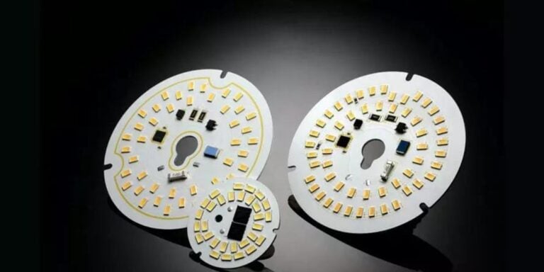
高出力 LED コンポーネント
高出力 LED はかなりの熱を発生し、配置精度に敏感です。 あい PCB LED アセンブリ、小さな整列エラーでも、はんだ接合部の信頼性と熱伝達に影響を与える可能性があります。 組み立てが不十分になると、熱応力が増加し、LED の寿命が短くなり、時間の経過とともに光出力が低下します。
接続モジュール (Wi-Fi、ZigBee、Bluetooth、マター)
ワイヤレス モジュールは、ノイズ、接地、物理的な配置に敏感です。 スマート照明では、さまざまな電力レベルで LED がオンとオフを切り替えても、接続が安定している必要があります。 アンテナのクリアランス、接地基準品質、はんだの一貫性などのアセンブリの決定は、信号の安定性に直接影響します。
マイクロコントローラと制御 IC
マイクロコントローラは、システムの頭脳として機能します。 調光曲線、自動化ルール、および他のデバイスとの通信を処理します。 スマート ライティング用のカスタム PCB アセンブリでは、これらのコンポーネントは、照明の動作を妨げる可能性のある電力の変動やタイミングの問題を避けるために、慎重に組み立てる必要があります。
スマート照明で使用されるセンサー
スマート照明には、モーション、周囲光、または環境センサーが含まれることがよくあります。 これらのコンポーネントは、LED の熱およびノイズ源から電気的に絶縁するために組み立てる必要があります。 組み立てが不十分な場合、センサー自体が適切に設計されていても、誤った測定値や不安定な動作につながる可能性があります。
スマート接続照明の重要なアセンブリに関する考慮事項
スマート照明アセンブリには、基本的な LED ボードには存在しない課題があります。 熱界面材料は、敏感な電子機器に干渉することなく、信頼できるヒート パスを作成する必要があります。 電力調整は、高 LED 電流と超低スタンバイ電力状態の両方を処理する必要があります。
シグナルの整合性は、もう 1 つの懸念事項 ワイヤレス モジュールは大電流 LED トレースと並んで動作するため、干渉のリスクが高まります。 はんだボイド、リフローの不均一、汚染などのアセンブリ エラーは、システム レベルでの照明と接続性の両方に影響を与えるため、後で修正することが困難になります。
組み立て段階では、信頼性はバランスに依存します。
- LED 熱経路と放熱
- 調光状態とスタンバイ状態での電力安定性
- ワイヤレス通信のシグナル インテグリティ
スマート LED PCB アセンブリの熱管理
熱管理は、スマート照明の信頼性を決定する要素です。 多くのスマート LED システムは、LED の効率的な熱拡散を提供するため、MCPCB またはアルミニウム基板を使用しています。 ただし、アセンブリの選択によって、その熱ポテンシャルが実際に実現されるかどうかが決まります。
スマート照明は、多くの場合、従来の照明よりも長いデューティ サイクルを実行します。 調光、センシング、および接続により、光出力が低下してもシステムはアクティブなままになります。 組み立て中に熱が正しく管理されないと、長期間の操作により、コンポーネントの老化が加速され、パフォーマンスが不安定になります。
スマート LED PCB の製造および組み立てワークフロー

スマート LED アセンブリの製造フローは、設計準備状況から始まります。ここでは、コンポーネントの配置が熱放散と信号の完全性の両方をサポートします。 アセンブリ シーケンスが重要です。 LED、制御 IC、および RF モジュールでは、異なる処理およびリフロー プロファイルが必要になる場合があります。
混合アセンブリは、LED はんだの要件と接続コンポーネントの熱制限とのバランスを取る必要があります。 検査は、はんだの品質だけでなく、基板全体の整列、清潔さ、一貫性にも重点を置いています。 このワークフローは、単純なコンポーネントの添付ではなく、システム統合を反映しています。
スマート接続照明アセンブリのテストと信頼性
目視検査だけでは、スマート照明アセンブリを検証することはできません。 機能テストでは、接続モジュールが確実に通信し、制御ロジックが負荷時に正しく応答することを確認する必要があります。 スマート照明システムの初期の多くの故障は、設計上の欠陥ではなく、限界はんだ接合部やサーマル インターフェイスの不良などのアセンブリの問題に起因します。
効果的なテストは通常、次のことに重点を置いています。
- LED 負荷の変化の下で安定した通信
- 通信バースト時の電源安定性
- 調光および自動化サイクル中の制御応答
テストは、基本的な検査では見えない照明、電力制御、通信の相互作用を明らかにするのに役立ちます。
スマート照明プロジェクトでよくある組み立てミス

よくある間違いの 1 つは、スマート LED ボードを標準の LED アセンブリのように扱うことです。 アセンブリ中の RF 動作を無視すると、接続が不安定になります。 もう 1 つの問題は、長期的な熱ストレスを過小評価していることです。 スマート照明システムは継続的に動作し、小さなアセンブリの弱点が時間の経過とともに信頼性の問題に陥ります。
電力供給と通信回線との相互作用を見落とすことも、もう 1 つのよくあるエラーです。 これらのミスにより、システムの安定性が低下し、フィールドの故障が増加します。
LED PCB アセンブリがどのように最新の照明システムをサポートしているか
スマート照明は、信頼性の高いアセンブリに依存して、一貫したパフォーマンスを実現します。 PCB LED アセンブリーにより、LED の寿命を損なうことなく、リモート制御、自動化、エネルギー管理が可能になります。 アセンブリが LED を整列し、電子機器を制御し、接続を単一のシステムとして使用すると、照明ネットワークは安定しており、予測可能で、スケーラブルなままです。
標準とスマート接続 LED PCB アセンブリの主な違い
以下の表は、システム レベルでの標準 LED PCB アセンブリとスマート コネクテッド LED PCB アセンブリの実際の違いを示しています。
| アスペクト | 標準の LED PCB アセンブリ | スマート接続 LED PCB アセンブリ |
| アセンブリの複雑さ | 低~中程度 | 混合部品による高性能 |
| コンポーネント統合 | LED と基本的なドライバー | LED、制御 IC、センサー、RF モジュール |
| テストの必要性 | 視覚的および電気的 | 機能、接続、および負荷テスト |
| 信頼性のリスク | ほとんど熱 | 熱、電力、信号の相互作用 |
結論
スマート コネクテッド ライティング用の LED PCB アセンブリは、単なる製造作業ではなく、システム レベルのプロセスです。 信頼性の高いスマート照明は、LED のパフォーマンス、熱管理、電力制御、および接続性のバランスをとる規律あるアセンブリに依存します。 アセンブリの品質がコア エンジニアリング要因として扱われると、スマート照明システムが安定した動作と長期的な信頼性を実現します。
よくある質問
関連記事