Español
 English
 简体中文
 Deutsch
 Français
 Italiano
 日本語
 한국어
 Polski
 Português
 Русский
 Türkçe
 Nederlands
 Tiếng Việt
 ไทย

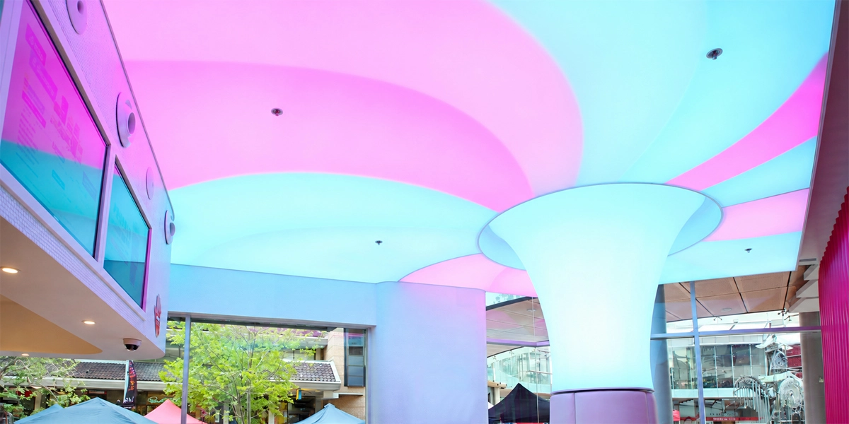
An RGB LED stretch ceiling places color-changing LED modules behind a translucent membrane. It turns the ceiling into a luminous surface for steady colors, zoned lighting or moving effects.
The choice of modules depends on how the ceiling will be used. A reception area with occasional color changes has different requirements from a pixel-mapped ceiling running animated patterns. Projects that also need everyday white lighting require a closer look at RGBW or RGBCW options.
This guide explains how to select the light source, plan module spacing and depth, and calculate DMX channels and power. Compare the available configurations in the SignliteLED LED module range.
Choose the Effect and the Color Channels
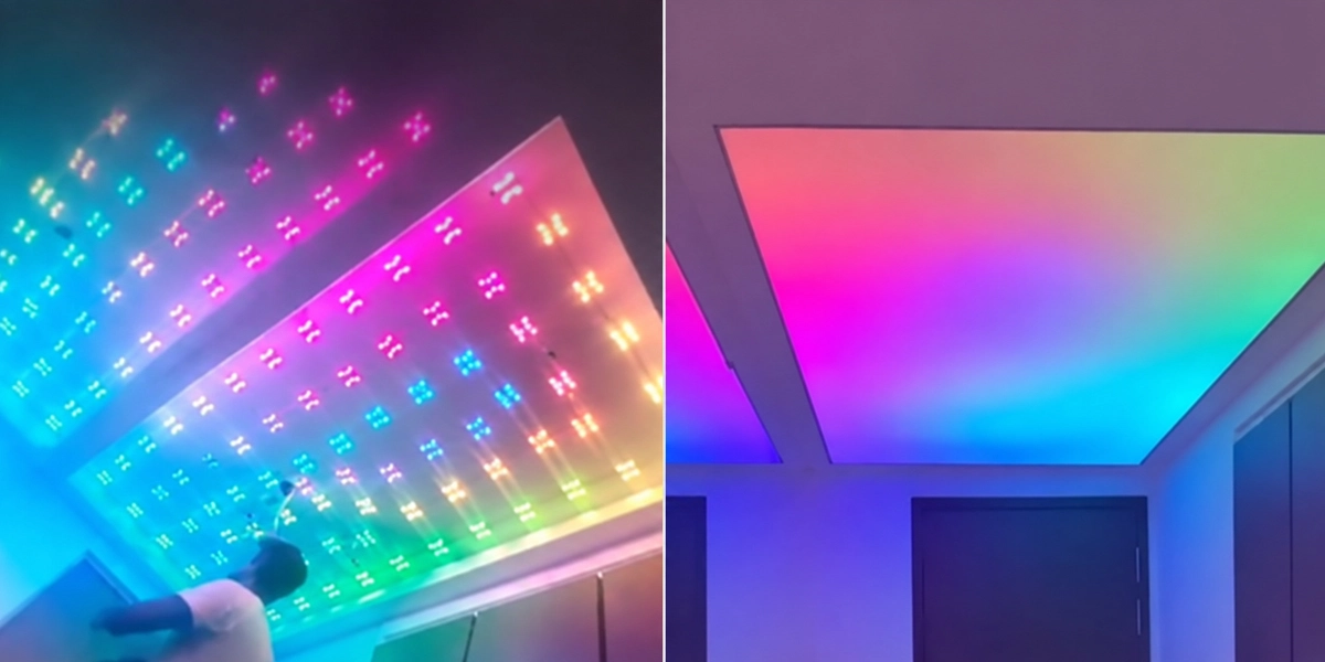
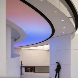
Start with a reference video. For a dynamic RGB stretch ceiling, it shows whether the whole surface changes color together, separate areas respond independently, or a pattern moves across the ceiling. Note the direction, speed and scale of the effect.
| Desired effect | What the system needs |
| Whole-ceiling color changes | Compatible LED modules controlled together |
| Different colors in separate areas | Independently controlled zones and a zone layout |
| Moving gradients or chase effects | Addressable modules, a pixel map and compatible playback |
| Everyday white lighting plus color scenes | RGBW or RGBCW modules with defined white-light requirements |
A ceiling used only for ambient color typically needs no dedicated white channel. If the ceiling also lights the room every day, specify the white scene’s brightness, color temperature and color rendering.
RGB, RGBW or RGBCW / RGBCCT LED Modules?
Choose RGB for colored lighting. Choose RGBW if the project also needs a dedicated white channel at a specified color temperature. For color effects and adjustable white light, choose a module with separate warm-white and cool-white channels, listed as RGBCW or RGBCCT. Confirm the channel configuration of the selected model before ordering.
Once you have chosen the color channels, compare the 24V RGBW and RGBCW / RGBCCT LED modules and check which models support your intended control method.
For ceilings that provide everyday lighting, test the white scene through the actual membrane at the intended brightness. Run the target color effect on the same sample to see how clearly the movement comes through.

Tensión de entrada: DC24V
Tipo de LED: 3030 SMD
Cantidad de LED: 6LED/módulo
Color: RGB+W (3000K/ 4000K/6000K)
Potencia: 4W/PCS
Tamaño: L 68mm* An 68mm
CRI: > 90
Ángulo de haz: 175°
IC: UCS512C4 (DMX512)
Cuerpo de carcasa: Aluminio
Garantía: 3 años de garantía
How Lens Choice Affects the Ceiling Layout
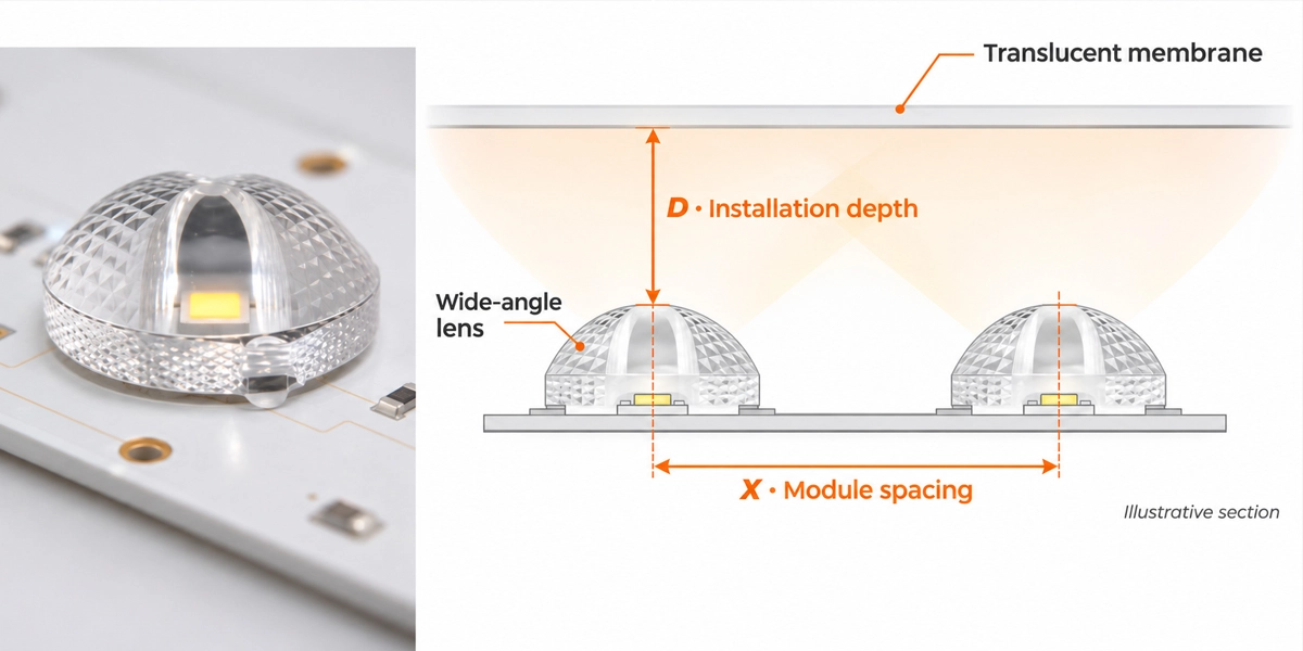
Wide-angle lenses for backlighting stretch ceilings spread each module’s output across the membrane. Evaluate the lens together with module spacing, installation depth and the finished surface’s light transmission.
A wide beam angle alone does not establish a minimum cavity depth or guarantee uniform illumination. The membrane, printed finish, mounting base and edge details also affect the result.
Define four dimensions on the drawing:
- X is the horizontal distance between module centers.
- Y is the vertical distance between module centers.
- D is the distance from the lens emitting surface to the membrane’s inner face.
- Edge distance is measured from the first module center to the illuminated boundary.
Use the actual membrane for testing. A layout approved behind one material can reveal hotspots or color differences behind another.
Backlit wall panels and light boxes need the same assessment, with attention to viewing positions, joints and edges. Our guide to LED modules and flexible LED sheets for backlit stretch ceilings compares the two options and explains how installation conditions affect the choice.
DMX LED Modules for Luminous Ceilings
DMX LED modules for luminous ceilings receive control data directly or operate through a compatible DMX decoder. Confirm the system architecture and channel mode before ordering.
Calculate the Channel Footprint
The channel footprint is the number of control channels a device requires in its selected mode. A basic RGBW mode uses four channels. A basic RGBCW mode uses five. Additional dimming or function channels increase the footprint.
One DMX universe contains 512 channels.
| Selected mode | cómpu | Independent modules per universe |
| Four-channel RGBW | 512 ÷ 4 | 128 |
| Five-channel RGBCW | 512 ÷ 5, rounded down | 102 |
The table shows how many independently controlled modules fit within one DMX universe. Use DMX universes and channel allocation to plan the address map, then check receiver loading, signal distribution, cable runs and power requirements separately.
Match Addresses to the Effect
Modules sharing an address range respond together. Moving patterns require independently controlled pixels or zones and a corresponding address map.
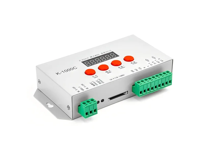
Confirm the footprint, address-setting method, universe count, scene storage and restart behavior. Check that the controller supports the required mapping and playback.
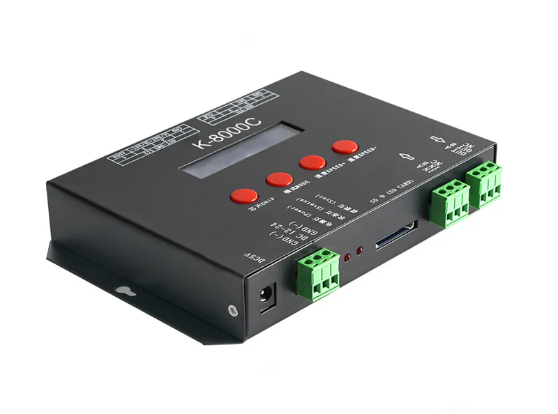
SPI addressable LED modules offer another route to pixel lighting. Compare specific products against module compatibility, wiring distances and maintenance requirements. Compare DMX and SPI LED controllers

A 24V DMX512 RGBCW LED module array displaying multiple colors before the stretch ceiling membrane is fitted.
A 20 m² Layout, Control and Power Example
Consider a 4m × 5m ceiling, with every RGBW module controlled independently.
Assume a 150mm center-to-center grid, with the first and last module centers no farther than half that spacing from the boundary. These are calculation assumptions, not a tested installation recommendation.
Estimate the Module Count and DMX Capacity
| Artículo | cómpu | Result |
| Rows across 4m | Round 4 ÷ 0.15 up | 27 |
| Columns along 5m | Round 5 ÷ 0.15 up | 34 |
| Module count | 27 × 34 | 918 |
| Channels at four per module | 918 × 4 | 3,672 |
| Universes at 128 modules each | Round 918 ÷ 128 up | 8 |
This assumes complete four-channel footprints within each universe and no extra function channels. Assign the modules across universes in the controller’s patch and pixel map.
The final drawing still needs the exact grid position, openings and maintenance access.
Check the Electrical Load
Use the selected module’s documented maximum simultaneous operating power. The following comparison shows how a change in that rating affects the same 918-module layout.
| Artículo | Assuming 4W per module | Assuming 8W per module |
| Total module load | 3,672W | 7,344W |
| Load per square meter | 183.6W/m² | 367.2W/m² |
| Supply capacity at load ×1.2 | 4,406.4W | 8,812.8W |
| Theoretical minimum number of 300W supplies | 15 | 30 |
The ×1.2 factor is an example capacity allowance. It corresponds to approximately 83.3% loading of the calculated supply capacity. Select the actual allowance using the supply’s derating requirements and installation conditions.
The supply counts are aggregate-capacity estimates. Power grouping, output-current limits, cable runs and voltage drop determine the final quantity.
For a module marked “4+4W,” confirm which channels the figures describe and whether they operate simultaneously. Use 8W only when the manufacturer confirms that maximum operating load.
This example also exposes a design issue. A 150mm grid with high-power modules produces substantial installed load. Review brightness, temperature and operating power before approving the layout.
Grouping modules under shared addresses reduces independently controlled pixels. It does not reduce the full-load rating of the installed modules.
Test Uniformity and Moving Effects Together
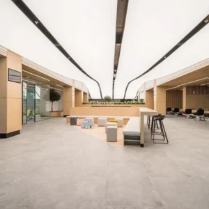
Backlit stretch ceiling lighting needs optical overlap to conceal individual light sources. Pixel effects need enough spatial definition for movement to remain recognizable.
A strongly diffusing membrane softens moving patterns. Wider spacing increases the risk of bright spots. Test both requirements using the intended material and layout.
For luminous ceiling lighting used throughout the day, assess white output, dimming and normal viewing positions. For architectural RGBW backlighting used mainly for atmosphere, also review color transitions and scene playback.
A representative sample includes neighboring modules, an edge and any important joint or change of shape.
| examinar | cheque |
| White scene | Hotspots, dark edges and differences between adjoining areas |
| Color scenes | Color appearance through the actual membrane |
| Moving effects | Recognizable direction, suitable speed and smooth transitions |
| Regulación | Stable appearance at intended operating levels |
| Restart | Expected scene and response after power returns |
Record the approved module, spacing, depth, membrane and settings. Use this record as the installation reference.

Plan Power and Wiring Before Closing the Ceiling
Select 24V constant-voltage LED power supplies using the documented load, installation conditions and manufacturer’s derating requirements. View 24V constant-voltage LED power supplies
Document each power group’s module count, load and feed points. Check conductor size, cable length and voltage drop. Add feeds and power supplies according to the approved wiring design.
Keep supplies, signal equipment and replaceable modules accessible after the membrane is fitted.
The handover package includes:
- Module layout and mounting details.
- Power-group schedule and wiring diagram.
- DMX address schedule or pixel map.
- Controller configuration and approved scenes.
- Replacement-module identification and access instructions.
What to Prepare for an RGB DMX Stretch Ceiling Proposal
A ceiling drawing shows the area and shape. The available installation depth, membrane specification and intended lighting effects help the supplier assess module spacing, DMX capacity and power distribution.
Confirm the Membrane Specification
Request the specification for the exact membrane and finish, including any printed graphics. The membrane affects brightness, color and how clearly moving patterns appear.
| Information | que confirmar |
| Fire classification | Test report, classification, intended use and installation conditions |
| Optical properties | Light transmission, diffusion, color appearance and relevant test conditions |
| Physical limits | Thickness, weight, maximum sheet area, seam requirements, temperature limits and clearances |
As a supplier-specific example, Stretch Ceilings lists a nominal thickness of 0.2 mm, a translucent membrane weight of 0.18 kg/m² and a maximum recommended sheet area of 50 m². It also publishes an EN 13501-1 B-s1,d0 classification. These are Stretch Ceilings’ published specifications. Their applicability depends on the membrane selected and the conditions documented in the relevant test report. Stretch Ceilings membrane specifications
Before ordering, confirm the membrane specification and required fire classification with the project team. Before closing the ceiling, verify the installed clearances and check that operating temperatures stay within the membrane supplier’s limits.
Gather the Project Details
- Ceiling drawing showing dimensions, shape and available installation depth.
- Membrane specification or sample with the selected finish.
- Reference effect video and any everyday white-light requirements.
- Control requirements covering the preferred system and how users will select scenes.
- Power and access plan showing proposed power-feed and controller locations and service access.
- Project scope including the number of ceilings or installation areas and the installation schedule.
Preguntas frecuentes
Conclusión
An RGB LED stretch ceiling starts with a clear lighting goal. Choose the color channels and control method around that goal, then check module spacing, installation depth, DMX capacity and power as one system. Approve the result with the actual membrane before full installation.
For help reviewing your design, send SignliteLED your ceiling drawing, available depth, membrane specification and reference effect video. Discuss your ceiling project
Publicaciones relacionadas