日本語
 English
 简体中文
 Deutsch
 Español
 Français
 Italiano
 한국어
 Polski
 Português
 Русский
 Türkçe
 Nederlands
 Tiếng Việt
 ไทย

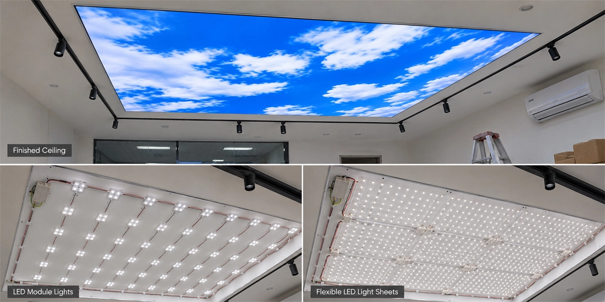
Backlit stretch ceiling lighting turns a translucent membrane into a large, diffused light surface. The finished ceiling may look simple, but its performance depends on the complete system: membrane transmission, cavity depth, LED spacing, optical distribution, surface reflectance, target brightness, power zoning and maintenance access.
Both systems can be installed behind a translucent stretch ceiling, but they distribute light in different ways. LED モジュール ライト form an adjustable grid of separate light points, while flexible LED light sheets provide a dense LED matrix on a thin flexible circuit.
Neither system is automatically better or less expensive.
Choose LED module lights when the project requires adjustable spacing, obstacle avoidance, replaceable strings or clearly divided electrical zones. Evaluate flexible LED light sheets when the ceiling void is shallow, the illuminated outline is irregular or a pre-arranged matrix reduces repeated positioning work.
Whichever system is selected, it must satisfy two different requirements:
- provide enough luminous output for the intended use;
- distribute that output evenly enough to avoid dots, bands and dark areas.
A layout can meet the lumen target and still fail the uniformity test. A dense layout can also achieve uniformity while producing more light and connected load than the project needs. The final quantity is determined by whichever requirement is more demanding.
What Determines Backlit Stretch Ceiling Lighting Performance?
Product selection begins with the ceiling construction rather than the LED category. The same light source can produce different results when the membrane, cavity or mounting surface changes.
Membrane Transmission and Target Brightness
A translucent membrane transmits light into the room while blending individual LEDs into one luminous surface.
A strongly diffusing membrane hides light points more effectively but usually reduces usable output. A highly transmissive membrane delivers more light while making irregular spacing easier to see. Printed graphics, colored films and double-layer constructions introduce additional losses.
について SignliteLED stretch ceiling lighting guide provides the following planning ranges for the installed LED source output behind a white stretch ceiling with approximately 50% light transmission:
| 申し込み | LED source luminous flux |
| 周囲の照明 | 500-1,000 lm/m² |
| 住宅用一般照明 | 1,000-2,000 lm/m² |
| Commercial or workplace lighting | 2,000-8,000 lm/m² |
These figures describe LED source output per square meter for that membrane condition, not measurements below the membrane. Dividing them by 50% again would count the transmission loss twice.
They also remain planning ranges rather than guaranteed results. The required output changes with membrane transmission, diffusion, room reflectance, ceiling height, printed graphics and the specified illuminance below the membrane.
Before selecting a layout, confirm the membrane manufacturer, stated transmission, color or print, single- or double-layer construction and whether the ceiling provides general lighting or only a decorative glow.
Depth, Pitch and Beam Distribution
Three dimensions influence how neighboring light pools blend:
- Mixing distance: the distance between the LEDs and membrane.
- LED pitch: the center-to-center distance between adjacent sources.
- Beam distribution: the actual intensity pattern produced by the LED or lens.
For an initial geometric check, the depth at which two ideal beam cones meet halfway between adjacent sources can be estimated with:
d = p ÷ (2 × tan(θ ÷ 2))
Where d is the geometric overlap depth, p is the LED pitch and θ is the nominal beam angle.
For a 120° source:
- 22.3 mm pitch gives approximately 6.4 mm;
- 100 mm pitch gives approximately 29 mm;
- 200 mm pitch gives approximately 58 mm.
These figures show only where ideal beam cones begin to overlap. They are not recommended installation depths. Beam angles describe photometric intensity boundaries rather than hard-edged cones, and simple overlap does not guarantee a uniform luminous surface.
This limitation becomes obvious with ultra-wide module lenses. A 68 mm pitch and nominal 175° lens produce a geometric result of about 1.5 mm, while SignliteLED’s practical starting guidance places the same lens in cavities tens of millimeters deep.
について SignliteLED LED module guide uses the following starting ranges:
| 空洞の深さ | Starting lens range |
| 50-80 mm | 175° |
| 80-120 mm | 160-175° |
| Above 120 mm | 160° or narrower |
The 50-80 mm practical cavity is roughly 33-53 times the 1.5 mm geometric overlap result. This difference shows why the formula is useful only as a lower-bound screening calculation.
For uniform ceiling backlighting, the same module guide uses approximately 100-120 mm spacing as a starting range. Spacing of 150-250 mm is associated with visible point-source or star effects rather than a continuous luminous ceiling.
Verify the final depth and spacing with a mock-up using the selected LED, mounting surface and membrane.
Comparing LED Module Lights and Flexible LED Light Sheets
Reference Product Specifications
Specific product data provides a clearer basis for comparison than general category descriptions. The following reference specifications are used in the calculations later in this guide. Available output, color configuration and control method vary by model.
LED モジュール ライト
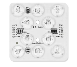
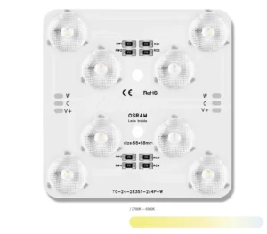
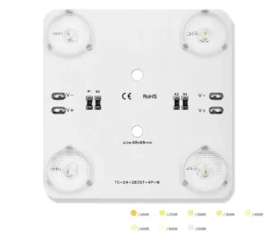
The reference LED module light measures 68 × 68 × 5.5 mm and operates at 24 V DC. Each module is rated at 4 W and approximately 600 lm. Its wide-angle optical design allows the module pitch to be adjusted according to the ceiling depth and uniformity target.
フレキシブルLEDライトシート
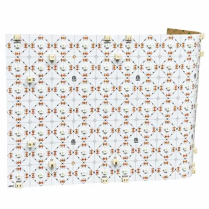
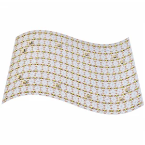
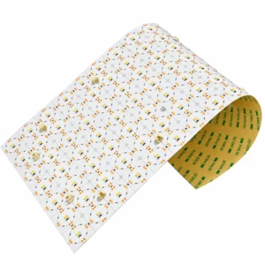
The reference flexible LED light sheet measures 490 × 245 mm and contains 242 LEDs in a 22 × 11 layout. Its approximate 22.3 mm LED pitch creates a dense lighting surface for shallow ceiling cavities. Each sheet is rated at 28 W and approximately 2,800 lm.
How the Two Systems Differ
| Decision factor | LED モジュール ライト | Flexible LED light sheets |
| Basic structure | Separate modules connected in strings or zones | Dense LED matrix on a flexible circuit |
| Spacing | Adjustable for the project | Defined by the sheet design |
| Obstacles | Individual modules can be repositioned | Openings and divided sections require planning |
| Shallow cavities | Depends on lens, pitch and membrane | 22.3 mm matrix supports short-distance mixing |
| Large regular areas | Repeatable grids are easy to zone | Multiple sheets cover a continuous area |
| Irregular areas | Modules follow the outline through repositioning | Sheets can be cut within the designed grid |
| 配線 | More individual points and string routing | Fewer large sections, but feeds increase after cutting |
| Local repair | Modules or strings can be isolated | Repair depends on sheet zoning and access |
| Main cost drivers | Quantity, fixing points, wiring and labor | Sheet count, connectors, cutting waste, feeds and labor |
Modules provide point-by-point layout control. They work well around sprinklers, air outlets, framing, sensors, speakers and access panels. Large ceilings can also be divided into clear electrical and maintenance zones.
The LED module light range includes single-color, tunable-white, RGBW and RGBCW products with static, SPI and DMX control options.
The limitation is installation density. Reducing module pitch increases product quantity, fixing points, wiring and branch connections. A low unit price does not guarantee a low installed cost.
Flexible LED light sheets replace separately positioned light points with a pre-arranged matrix. Their dense layout is useful in shallow cavities, irregular luminous areas and projects where positioning thousands of modules would consume excessive labor.
The sheet cannot be cut at arbitrary locations. Every cut must follow the circuit grid and preserve a valid electrical path. Divided sections may need extra connectors and separate power feeds.
The flexible LED light sheet range includes single-color, tunable-white, RGB and RGBW products. The カット可能なマトリックス LED ライト シート ガイド explains the cutting and connection layout.
How to Choose by Ceiling Conditions
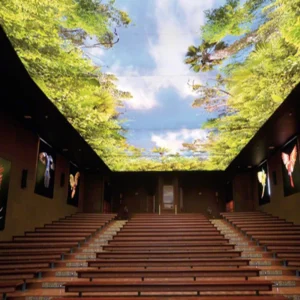
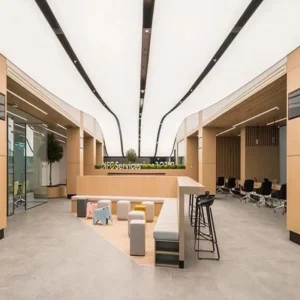
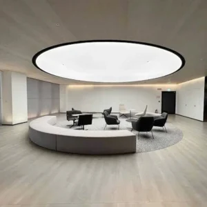
Ceiling geometry determines how much room the light has to mix, how easily the sources can avoid obstructions and how the system can be divided into serviceable zones.
Shallow Ceiling Voids
A shallow cavity leaves less space for neighboring light pools to blend.
The reference LED sheet has a 22.3 mm matrix and 120° beam. Its ideal beam cones begin to overlap after approximately 6.4 mm, giving the sheet a clear density advantage. The usable cavity must still be deeper because visual uniformity requires more than geometric contact between beams.
Wide-angle modules can also work in shallow cavities. SignliteLED uses a 175° lens as the starting option for cavities of approximately 50-80 mm. Test the module layout at the intended pitch rather than judging it from the beam angle alone.
A brighter source cannot correct inadequate optical mixing. Increasing output may make visible dots more obvious.
Large Regular Ceilings
A repeatable module grid is practical when the ceiling is rectangular, cavity depth is consistent and electrical zones are easy to plan. Module spacing can be adjusted after testing to balance uniformity, quantity and connected load.
Light sheets can cover the same area, but large projects may require hundreds of sheets. Each sheet still needs alignment, connection and testing. The claim that sheets always save labor must therefore be checked against the actual area and layout.
Divide large ceilings into manageable electrical and maintenance zones instead of wiring the entire surface as one circuit.
Curves, Irregular Boundaries and Building Services
Modules can follow curves through individual repositioning and can be moved around penetrations without cutting a large circuit.
Light sheets reduce unused illuminated area around irregular outlines, but each cut changes the electrical layout. Count the resulting sections, connectors and feeds before assuming the sheet solution is simpler.
A hybrid system is also possible: modules across a regular main area and sheets in shallow edges, curves or difficult sections. Match voltage, white point, dimming behavior and control architecture across both systems.
Sprinklers, air-conditioning outlets, sensors, speakers and access panels must be plotted before the product quantity is calculated. Maintain all mechanical, fire-protection and electrical service clearances.
Control, Power, Installation and Testing
A luminous ceiling has to work as an optical system and as an electrical installation at the same time. Product selection, power distribution, control and maintenance access therefore need to be planned as one system.
White, Tunable White, RGBW or DMX
A fixed-white ceiling normally requires switching or dimming only. Tunable-white systems require two-channel products and compatible controllers. RGBW and RGBCW systems add conductors and control channels while retaining a dedicated white channel.
SPI or DMX is useful when the project requires addressed zones, synchronized scenes, animated gradients, pixel effects or integration with a lighting desk or building-control system.
Let the required visual effect determine the protocol. Adding addressable control without a defined purpose increases wiring, commissioning and maintenance.

入力電圧DC24V
LED タイプ: 3030 SMD
LED 数量: 6LED/モジュール
色: RGB+W (3000k/4000k/6000k)
電源: 4W/個
サイズ: L 68mm* W 68mm
CRI: > 90
ビーム角: 175°
IC: UCS512C4 (DMX512)
ハウジング本体: アルミニウム
保証: 3 年間の保証
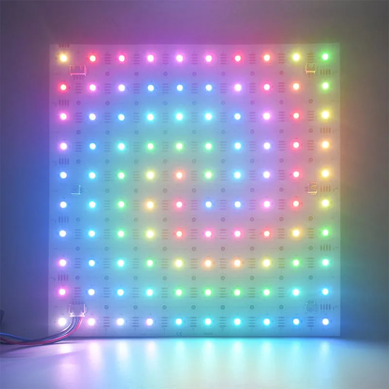
アドレス指定可能な LED シート
サイズ(長さ×幅):250mmx250mm
LED タイプ: 5050 SMD
LED 数量: 100 個
IC タイプ: WS2812 に組み込まれています
IC 数量: 100pcs
色: RGBIC
動作電圧: DC 12V
現在の: 1.08A
電力: 13W
光束: 20LM/LED
ビーム角: 120°
防水レベル: IP20 非防水、IP54 防水
保証: 3 年
Power-Supply Sizing and Wiring Zones
For the referenced module systems, SignliteLED recommends a minimum power-supply capacity of:
Required capacity = connected LED load × 1.2
An 800 W LED load therefore requires at least 960 W of rated power-supply capacity, normally rounded up to the next practical size.
Distribute this capacity across multiple accessible circuits on large ceilings. Confirm cable sizes, current per branch, voltage drop, power-injection points and controller capacity before installation.
Keep power supplies, controllers and major junctions accessible after the membrane is fitted.
インストール要件
For module layouts, count every fixing point, module string, cable route, branch connection and test point. Order approximately 3-5% additional modules as project spares, preferably from the same model and color bin.
For light sheets, count full sheets, cut sections, connectors, power feeds, alignment points and unusable offcuts. Keep matching replacement sheets or cuttable sections for future service.
Adhesive-backed sheets require a flat, clean and dry mounting surface. Dust, oil, loose paint, rough texture or poor heat dissipation can cause adhesion and reliability problems. Clean and prepare the surface before installation; the adhesive backing cannot compensate for an unsuitable substrate.
Mock-Up and Uniformity Acceptance
Build a representative mock-up with the actual LED source, mounting surface and membrane.
Passing the lumen calculation is not enough. The mock-up must also show that the complete luminous ceiling remains visually uniform at the intended operating level.
Separate optical checks from electrical checks.
Optical checks:
- LED dots;
- bright bands between rows;
- dark lines between sheets;
- edge falloff;
- shadows around obstacles;
- visible cutting or joining boundaries.
Electrical checks:
- brightness differences between zones;
- voltage-drop-related dimming;
- color-temperature variation;
- inconsistent dimming;
- unstable SPI or DMX data.
As a practical SignliteLED screening rule for an evenly illuminated ceiling:
maximum measured illuminance ÷ minimum measured illuminance ≤ 3
The brightest measured point must remain within three times the dimmest point unless the project specifies a stricter criterion. Measure multiple positions with a lux meter and repeat the test at full output and the intended operating level.
This 3:1 screening rule does not apply to star-effect ceilings because visible point sources are intentional.
Thermal, Fire-Safety and Maintenance Checks
Confirm that the membrane, support structure, wiring and electrical equipment meet the fire and safety requirements applicable to the project.
Check the permitted operating temperature of the LEDs and power supplies, allow ventilation around drivers and controllers, and use a mounting surface suitable for heat dissipation. Do not cover modules, sheets, drivers or connectors with insulation unless the selected product and installation method specifically allow it.
Humid or exposed areas require an appropriate IP rating. Local building, fire and electrical requirements take priority over general product guidance.
Record the final model, spacing, power zones and wiring layout. The final design must allow a technician to locate and repair a fault without opening the complete ceiling.
Quantity, Power and Labor: A 100 m² Example
This example separates three different constraints:
- the luminous output required for the space;
- the source density required for uniformity;
- the installation work created by the resulting layout.
Flexible LED Light Sheet Calculations
One 490 × 245 mm sheet covers:
0.49 × 0.245 = 0.12005 m²
A theoretical full-coverage layout for 100 m² requires:
100 ÷ 0.12005 ≈ 833 sheets
Using the 28 W, 2,800 lm single-color sheet:
| Sheet layout basis | 量 | 接続負荷 | 電力密度 | LED source output |
| 2,000 lm/m² planning level | 72 sheets | 2.02 kW | 20 W/m² | Approximately 2,016 lm/m² |
| 8,000 lm/m² planning level | 286 sheets | 8.01 kW | 80 W/m² | Approximately 8,008 lm/m² |
| Geometric full coverage | 833 sheets | 23.3 kW | 233 W/m² | Approximately 23,324 lm/m² |
The first two rows satisfy the source-lumen calculation only. They do not prove that the sheets can be distributed across 100 m² without visible gaps or dark areas.
Seventy-two sheets physically cover only about 8.6 m², while 286 sheets cover about 34.3 m². The final quantity may therefore be determined by uniformity rather than total lumens.
Edge-to-edge geometric coverage of 100 m² requires the full 833 sheets. The resulting 233 W/m² is installed capacity at full output, not the expected operating power for every project.
If the complete layout is dimmed from its full source output of approximately 23,324 lm/m² to the 8,000 lm/m² planning level, the ideal proportional load is about 80 W/m². At 4,000 lm/m² it is about 40 W/m², and at 2,000 lm/m² it is about 20 W/m².
This simplified comparison assumes approximately linear dimming and excludes driver losses. It also does not mean that full edge-to-edge coverage is required in every ceiling. Sheet spacing and quantity can be reduced only after the membrane mock-up confirms uniformity.
LED Module Calculations
Using a 4 W module at the 150 lm/W version gives approximately 600 lm per module.
| Module layout basis | Quantity for 100 m² | Approximate pitch | 接続負荷 | 電力密度 |
| 2,000 lm/m² planning level | 334 modules | 547 mm | 1.34 kW | 13 W/m² |
| 8,000 lm/m² planning level | 1,334 modules | 274 mm | 5.34 kW | 53 W/m² |
| 120 mm uniformity starting pitch | 6,944 modules | 120mm | 27.8 kW | 278 W/m² |
| 100 mm uniformity starting pitch | 10,000 modules | 100mm | 40 kW | 400 W/m² |
The first two rows meet the source-lumen calculation but create spacing associated with visible point sources. They are not automatically suitable for a continuous luminous ceiling.
At 120 mm pitch, 6,944 modules produce approximately 41,700 lm/m² at full output when the 150 lm/W version is used. Reducing the system to the 8,000 lm/m² planning level gives an ideal proportional load of about 53 W/m².
Under the same simplified assumptions, the module system uses less operating power than the full-coverage sheet layout at the 8,000 lm/m² level, approximately 53 W/m² versus 80 W/m². However, the module grid requires more installed capacity, approximately 278 W/m² versus 233 W/m².
This comparison assumes the 150 lm/W module, linear dimming and equal LED source-output targets. Driver efficiency, control losses and membrane performance can change the measured input power. The mock-up still determines whether the 120 mm module pitch and the proposed sheet spacing provide equivalent uniformity.
This is the central engineering trade-off:
Brightness determines the minimum output. Uniformity determines the maximum usable spacing. The final layout must satisfy both.
What This Means for Labor and Purchasing
Light sheets reduce individual LED positioning, but a large project still requires hundreds of sheets, connectors and alignment points. Modules provide flexible placement, but a uniform grid may require thousands of fixing points and cable connections.
Neither system is cheaper based on unit price or watts alone. Compare systems designed to deliver the same membrane brightness and uniformity, then include power supplies, controllers, wiring, mounting materials, cutting waste, installation labor, commissioning, spare parts and service access.
What to Send for a Backlit Stretch Ceiling Lighting Proposal
Provide:
- illuminated length and width;
- distance from the LED mounting surface to the membrane;
- ceiling plan and section drawing;
- membrane manufacturer and reference;
- membrane color, construction and transmission;
- single- or double-layer design;
- locations of HVAC outlets, sprinklers, framing and access panels;
- required illuminance or visual effect;
- fixed white, tunable white, RGBW or dynamic control;
- preferred voltage and control protocol;
- environmental and fire-safety requirements;
- project quantity and installation schedule.
A section drawing and physical membrane sample are usually more useful than a completed-ceiling photograph.
よくある質問
結論
Use the following decision order:
- define the membrane and required lighting effect;
- establish the LED source-output range;
- calculate an initial layout from real product data;
- check whether that layout can achieve uniformity;
- build a representative mock-up;
- size the power system with at least 20% capacity margin;
- compare installation labor, spare parts and future access.
The final layout must pass both the brightness calculation and the uniformity test. The best solution is the complete system that achieves the required luminous surface with practical installation, controlled power and maintainable electrical zones.
関連記事