3–5 day fast prototyping in LED PCB assembly refers to producing a functional, limited-quantity LED PCB sample within a compressed manufacturing window. It does not mean skipping steps or rushing incomplete designs. Turnaround speed depends on design readiness, confirmed component availability, and a clearly defined assembly scope. When these conditions align, accelerated prototype builds are achievable without changing the underlying manufacturing process.
What “3–5 Day Fast Prototyping” Means in LED PCB Assembly

Fast prototyping describes a controlled shortcut through standard lead times, not a shortcut through engineering discipline. The output is a prototype, not a production-ready batch. The goal is validation, not volume.
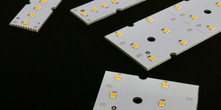
LED PCB assembly carries tighter constraints than many other board types. Thermal paths, LED placement accuracy, and current consistency matter immediately, even at the prototype stage. Because of this, fast prototyping focuses on boards that are already manufacturable, not designs still being explored.
In practical terms, 3–5 day fast prototyping usually includes fabrication of bare boards, placement of available LED and driver components, and basic functional verification. It excludes process tuning, extended burn-in, and cosmetic optimization that belong to later stages.
Typical Workflow Behind Fast LED PCB Prototyping

Fast turnaround is possible only when the workflow remains predictable. The process does not change, but priorities do.
Design readiness is the first gate. Files must be final, internally reviewed, and free of open questions. There is no time buffer for clarification cycles.
Component sourcing follows reality, not intent. Only parts that are in stock, approved, and already qualified for assembly can be used. Substitutions slow everything.
Assembly prioritization happens at the scheduling level. Prototype jobs are slotted into existing lines between production runs or assigned to dedicated fast-turn capacity.
Testing scope is intentionally limited. The objective is confirmation that the board functions as designed, not full reliability characterization.
Speed is achieved by reducing uncertainty, not by compressing physics.
Factors That Enable 3–5 Day Turnaround
1. Design Completeness and Manufacturability
A complete design is the single strongest predictor of fast delivery. Gerbers, pick-and-place data, and BOMs must align without interpretation. LED boards that already follow standard footprints, spacing rules, and thermal strategies move quickly.
- Minor layout errors often cause full schedule resets
- DFM clarity matters more than design novelty
2. Component Availability for LED Assemblies
LED components are not interchangeable at the last minute. Optical bins, voltage classes, and package types limit flexibility. Fast prototyping relies on components that are already stocked or locally sourced.
- Long-lead LEDs remove any chance of 3–5 day builds
- Driver IC availability often becomes the bottleneck
3. Assembly Line Configuration for LED Boards
Not all SMT lines are equally suited for LED work. Boards requiring special handling, high copper weight, or thermal interface steps slow throughput. Lines already configured for LED placement enable faster transitions between jobs.
4. Testing and Inspection Limits
Fast prototypes undergo focused inspection. Electrical checks and basic functional validation are typical. Extended aging, photometric measurement, or environmental testing are deferred. This limitation is intentional and necessary to protect timelines.
When 3–5 Day LED PCB Prototyping Is Realistic — and When It Is Not
Fast prototyping is realistic for simple to moderately complex LED PCB designs that reuse known architectures. Linear LED modules, basic driver integrations, and single-board layouts fit well within accelerated timelines.
It becomes unrealistic when designs introduce multiple LED types, novel thermal structures, or unproven layouts. Each added variable increases coordination effort and risk.
Missed timelines usually come from expectation gaps. Engineers expect speed despite unresolved design details. Procurement expects speed despite uncertain component supply. Manufacturing can only move as fast as inputs allow.
Understanding these boundaries prevents frustration on all sides.
Role of LED-Specific Assembly Considerations
PCB LED assembly introduces constraints that affect speed even at the prototype stage. LED placement accuracy directly impacts optical performance and cannot be treated casually. Rework is limited once LEDs are mounted.
Thermal paths must be continuous and intentional. Poor thermal interfaces reveal themselves quickly during initial power-on, often halting further testing.
System-level behavior matters early. Even prototypes must manage heat spread, current balance, and mechanical alignment. These realities explain why LED fast prototyping rewards mature designs and penalizes exploratory ones.
How Fast Prototyping Supports Custom PCB Assembly Decisions

Fast prototypes exist to reduce uncertainty before commitment. Engineers use them to verify layout assumptions, confirm electrical behavior, and observe thermal response under real conditions.
From a decision standpoint, custom pcb assembly planning benefits from early signals. A prototype may confirm that a design is ready to scale or reveal that a revision is required before volume investment.
Procurement teams also benefit. Early builds expose sourcing risks and help validate whether planned components support realistic schedules.
Fast prototyping is not about speed alone. It is about informed decision-making.
How Fast Prototyping Fits Into Custom PCB Fabrication Pipelines
Fast prototyping occupies a narrow but critical position in the broader custom pcb fabrication flow.
| Stage | Purpose | Speed Expectation |
| Prototype | Functional validation | Fast, limited scope |
| Validation | Design refinement | Standard |
| Revision | Issue correction | Variable |
| Scale | Stable production | Planned lead times |
Fast prototyping ends once design confidence is established. Standard fabrication begins when consistency, yield, and repeatability become priorities.
Trying to stretch fast-turn methods into production creates quality and scheduling risks.
Common Misunderstandings About Fast PCB Prototyping
One common belief is that fast means low quality. In reality, quality depends on design discipline, not schedule length. Fast prototypes meet defined checks but avoid unnecessary ones.
Another misunderstanding is that every design qualifies. Fast turnaround favors designs that are already stable. Early-stage concepts rarely fit.
A third assumption is that prototypes represent the final product. Prototypes answer questions. They do not define production readiness on their own.
Clarifying these points prevents misaligned expectations.
Conclusion
3–5 day fast prototyping in LED PCB assembly means producing a functional LED PCB prototype within a compressed but controlled timeframe. It depends on design readiness, component availability, and limited assembly scope. It is not a promise of speed for every project, nor a substitute for standard production processes. When used correctly, fast prototyping provides early technical insight and supports better custom pcb production decisions.
FAQs
Related Posts