In modern lighting design, achieving uniform light distribution is no longer a visual preference. An optimized PCB LED layout ensures consistent brightness, reduced glare, and improved visual comfort. Beyond aesthetics, layout optimization directly influences thermal performance, electrical efficiency, and product lifespan. Improper LED placement often causes hotspots, uneven illumination, color variation, and accelerated component degradation.
Optimizing PCB LED layout extends beyond simple placement, requiring optical, thermal, and electrical planning. Balanced material selection and precise routing ensure each LED contributes evenly to final output. Poor layout choices create hotspots, shadowing, color inconsistency, and early failures reducing reliability.
This blog explores design principles for optimizing LED PCB board layouts achieving uniform light distribution. It covers LED spacing strategies, beam angle control, and optical alignment techniques. Thermal pathways and substrate choices are explained to improve durability and long-term lighting performance.
Understanding Uniform Light Distribution in LED Products
Uniform light distribution refers to the even spread of luminous intensity across the intended illuminated area, without visible brightness variations. In practical LED products, non-uniformity typically appears as:
- Bright spots directly above LEDs
- Dark areas between LEDs
- Uneven edge illumination
- Glare caused by concentrated light points
These problems are usually not caused by the LED chips themselves, but by suboptimal PCB layout, spacing, and thermal imbalance.
Role of PCB Layout in LED Light Uniformity
The PCB is the physical platform that determines:
- LED placement geometry
- Spacing between LEDs
- Electrical current distribution
- Thermal dissipation paths
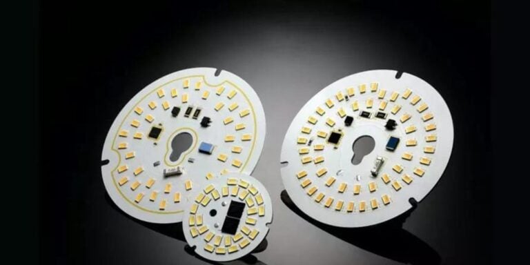
Because LEDs are point light sources, their arrangement on the PCB dictates how light overlaps and blends before reaching diffusers, lenses, or open air. A poorly planned layout can cause localized brightness peaks, while an optimized layout ensures smooth light blending.
LED Spacing and Pitch Optimization
1: Importance of Proper LED Spacing
LED spacing, often referred to as LED pitch, is the distance between adjacent LEDs on the PCB. Incorrect spacing is one of the most common causes of uneven light output.
(a) Too close spacing
- Creates excessive brightness concentration
- Increases thermal density
- Leads to glare and optical discomfort
(b) Too wide spacing
- Causes dark spots between LEDs
- Requires stronger diffusers
- Reduces overall efficiency
The optimal spacing depends on LED power, beam angle, mounting height, and optical components used in the final product.
2: Matching Spacing to Optical Design
For products using diffusers or lenses, LED spacing must align with the diffuser’s light-mixing capability. High-diffusion materials allow slightly wider spacing, while low-diffusion designs require tighter LED placement to maintain uniformity.
Symmetrical and Consistent LED Placement
Importance of Layout Symmetry
Symmetrical LED placement ensures balanced light distribution across the PCB surface. Asymmetrical layouts often result in uneven brightness, especially near edges or corners.
Key principles include:
- Equal spacing in X and Y directions
- Consistent alignment patterns (grid or circular)
- Avoiding random or irregular LED positioning
In linear lighting products, LEDs should follow a straight, evenly spaced line. In panel or area lighting, matrix or staggered grid layouts are preferred to improve light overlap.
Edge and Corner Illumination Control
Edges and corners are common problem areas where light output tends to drop off. Poor edge illumination makes products appear dimmer and lower in quality.
To address this:
- Place LEDs closer to PCB edges
- Use slightly higher-density placement near corners
- Maintain thermal balance to avoid overheating edge LEDs
This ensures consistent brightness across the entire emitting surface.
Current Distribution and Electrical Balance
Uniform Current Equals Uniform Light
Even if LEDs are perfectly spaced, uneven current distribution can still cause brightness variations. LEDs connected to different current paths may operate at slightly different currents, leading to inconsistent light output.
Best practices include:
- Balanced series-parallel circuit design
- Equal trace lengths for parallel LED strings
- Avoiding excessive voltage drops across long traces
Uniform electrical design ensures each LED operates at the intended power level.
Thermal Uniformity and Its Impact on Light Output
1: Relationship Between Heat and Brightness
LED brightness is directly affected by junction temperature. LEDs running hotter produce less light and degrade faster. Uneven heat distribution across the PCB therefore leads to uneven light output over time.
2: Thermal-Aware LED Layout
To maintain uniform brightness:
- Distribute LEDs evenly to avoid thermal hotspots
- Avoid clustering high-power LEDs in one area
- Use consistent thermal paths for all LEDs
Uniform thermal performance ensures consistent luminous output throughout the PCB.
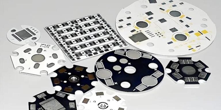
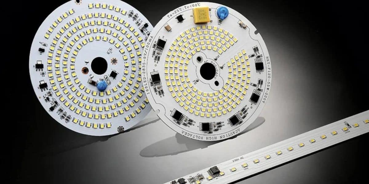
PCB Material and Its Influence on Layout Effectiveness
While layout geometry is critical, PCB material plays a supporting role in maintaining uniformity. PCBs with better thermal conductivity help equalize temperature differences across the board, reducing brightness variation caused by heat buildup.
Metal-core PCBs, particularly aluminum-based designs, are commonly used in high-power LED products because they support consistent thermal behavior across the layout.
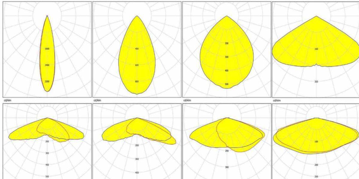
Optical Interaction Between LEDs
Light Overlap and Blending
Uniform illumination relies on controlled overlap of individual LED light patterns. Proper PCB layout ensures that each LED’s beam overlaps with neighboring LEDs at the correct angle and distance.
Designers must consider:
- LED viewing angle
- PCB-to-diffuser distance
- Reflective surfaces within the product housing
Optimized layout reduces the need for excessive diffusion, improving efficiency while maintaining uniformity.
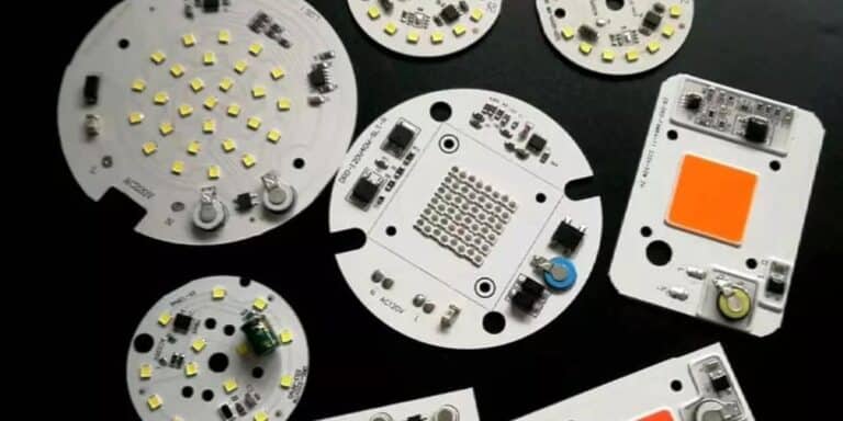
Layout Considerations for Different LED Products
1: Linear LED Products
- Use consistent, straight-line LED spacing
- Maintain equal distance from diffuser
- Avoid gaps near ends
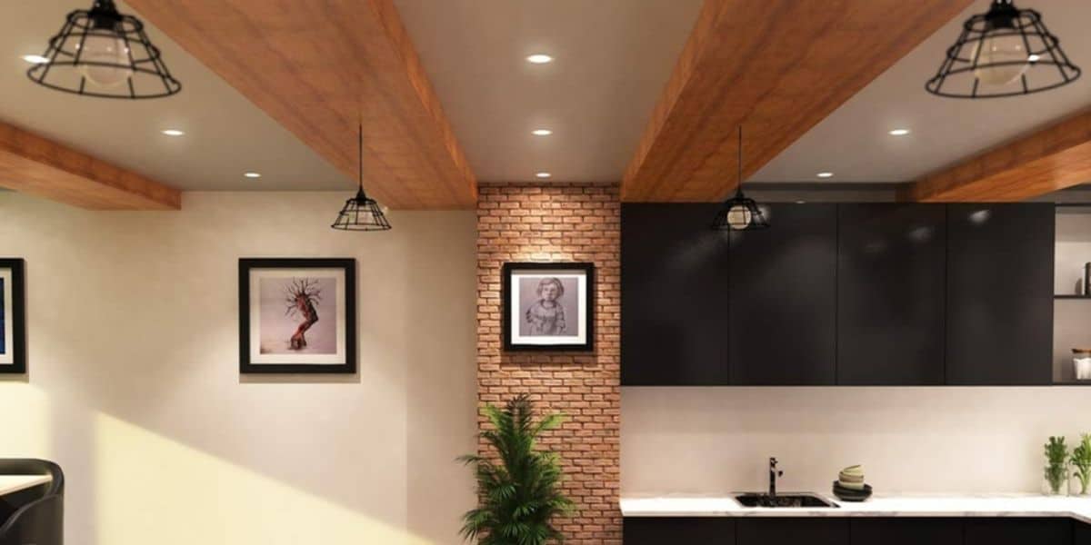
2: Panel and Ceiling Lights
- Use grid or staggered matrix layouts
- Increase edge LED density if required
- Balance center and perimeter illumination
3: High-Power Spot or Flood Lights
- Use symmetrical circular layouts
- Ensure thermal balance around the center LED
- Avoid over-driving central LEDs
Each product category requires a layout tailored to its optical and mechanical design.
Minimizing Visual Artifacts
Poor PCB LED layout can cause unwanted visual artifacts such as:
- Dotting effect (visible LED points)
- Zebra striping in linear fixtures
- Shadow bands on illuminated surfaces
Optimized layout, combined with correct diffuser selection, eliminates these defects and enhances perceived product quality.
Testing and Iteration in Layout Optimization
Achieving perfect uniformity often requires prototyping and testing. Simulation tools can predict light distribution, but real-world testing validates assumptions.
Recommended steps include:
- Optical simulation of LED placement
- Thermal analysis of PCB layout
- Physical prototyping and photometric testing
- Iterative refinement based on results
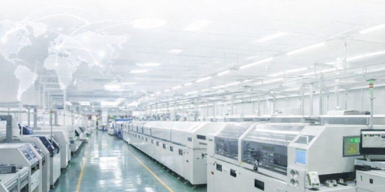
This systematic approach ensures reliable, repeatable light uniformity in mass production.
Why Should You Consider SignliteLED For Your Next Partner?
For superior lighting solutions and dependable LED performance, SignliteLED specializes in high-quality PCB LED solutions engineered for precision and durability.
- Our experienced team develops advanced LED PCB board design layouts that ensure uniform brightness, electrical stability, and long-term reliability.
- By utilizing premium materials such as SMD LED PCB board and round aluminum PCB LED, we achieve excellent thermal management and improved heat dissipation.
- Our customized LED light PCB design approach supports scalable production, making our custom LED PCB solutions ideal for commercial, industrial, and architectural lighting applications.
Conclusion
Optimizing PCB LED layout is fundamental to achieving uniform light distribution in LED products. Proper LED spacing, symmetrical placement, balanced current design, and thermal uniformity all work together to deliver smooth, glare-free illumination. In short, uniform light does not happen by chance. It is the result of precise, thoughtful PCB LED layout design.
Contact SignliteLED today to discuss your project requirements and experience high-quality, durable LED PCB manufacturer tailored to your applications.
FAQs
Related Posts