Electric vehicle charging systems and solar PV installations face a different surge risk profile than conventional electrical loads. Bidirectional power flow, frequent DC–AC conversion, and dense power electronics make these systems sensitive to both external grid disturbances and internally generated transients. Effective protection depends on coordinated, layered use of a surge protection device across DC and AC zones, not reliance on a single point of defense.
Why EV & Solar Systems Face Higher Surge Risk

Solar PV systems are exposed at the DC side in a way most electrical installations are not. Long PV string cables act as antennas for fast-rising overvoltages, while high DC operating voltages reduce the margin for error when transient stress appears. Even without direct lightning involvement, induced and switching-related surges can reach damaging levels.
Inverters sit at the center of this risk. They continuously switch between DC input and AC output using high-frequency power semiconductors. These devices are efficient but unforgiving. Repetitive voltage spikes accelerate insulation wear, degrade semiconductor junctions, and shorten service life long before catastrophic failure occurs.
EV chargers add another layer of vulnerability. From the grid’s perspective, an EV charger is not a passive load. It is a controlled power conversion system with rectifiers, DC link capacitors, control logic, and communication interfaces. Grid switching events, utility faults, or nearby large-load operations can inject disturbances that propagate directly into these sensitive stages.
Crucially, many damaging events are not dramatic. Routine switching, capacitor bank engagement, or inverter commutation can generate surges that accumulate stress over time. This reminder matters because protection strategies must address frequent, moderate transients, not just rare extremes.
Surge Protection Strategy for Solar PV Systems

Surge protection in solar installations should be approached by system zones rather than individual components. Each zone has a different exposure profile and requires a specific protection role.
DC-side protection between PV strings and inverter
The DC side of a PV system is continuously energized during daylight and often operates at hundreds or thousands of volts. A properly selected dc spd installed between the PV array and the inverter provides a controlled path for transient energy to divert away from inverter inputs.
Key points to consider:
- DC circuits experience sustained voltage, so the SPD must be designed specifically for DC behavior.
- Cable length and routing increase exposure to induced transients.
- Protection close to the inverter limits the residual voltage that reaches sensitive electronics.
A surge protection device for solar panel circuits is not about stopping surges but about limiting voltage to a level the inverter can tolerate repeatedly.
AC-side protection at inverter output
Once power is converted to AC, the inverter output becomes exposed to grid-originated disturbances. Switching events upstream, utility faults, or nearby industrial loads can introduce surges that travel back toward the inverter.
An ac spd installed at the inverter output or main distribution interface serves to clamp these overvoltages before they stress the inverter’s output stage and internal DC link. This is especially important in grid-tied systems where power flows both directions depending on operating conditions.
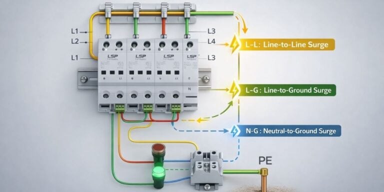
Why coordination between DC and AC SPDs matters
DC-side and AC-side devices do not work independently. Poor coordination can lead to uneven energy sharing, excessive stress on one device, or elevated residual voltage reaching the inverter.
Good coordination ensures:
- The DC-side SPD manages array-originated transients.
- The AC-side SPD handles grid-originated disturbances.
- Residual voltages are progressively reduced as surges propagate through the system.
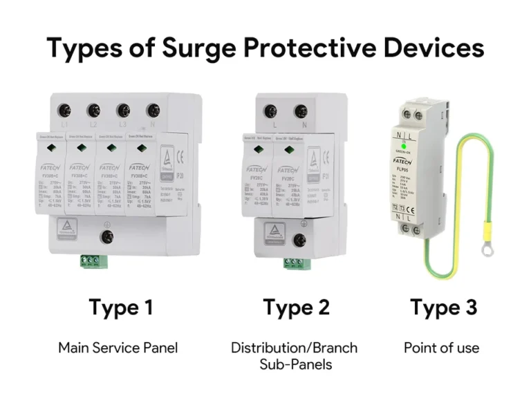
Role of surge protective device type 2 in solar installations
In most fixed PV installations, a surge protective device type 2 is appropriate for both DC and AC locations. These devices are designed to handle repetitive transient energy associated with switching and indirect lightning effects without requiring the extreme discharge capacity reserved for service entrance scenarios.
Why Type 3 is only used downstream for electronics
Type 3 devices are intended for low-energy residual surges and should never be installed as the only protection measure. In solar systems, they may be used downstream to protect monitoring electronics or communication interfaces, but only when upstream protection already limits surge energy.
Surge Protection Strategy for EV Charging Systems

EV charging systems should be analyzed from a power-flow perspective, starting at the grid connection and ending at the vehicle interface.
Grid to distribution panel to EV charger
Surges typically enter through the AC supply. An ac spd at the distribution panel feeding the EV charger reduces the amplitude of incoming transients. This is the first layer of defense and is especially important where chargers are connected to long feeder runs or outdoor equipment.
Internal power electronics sensitivity
Inside the charger, AC is rectified to DC, processed through DC link stages, and regulated by high-speed switching devices. These stages are sensitive to overvoltage, particularly repetitive spikes that degrade capacitors and semiconductors over time.
Without upstream voltage limitation, internal components are forced to absorb stress they were never designed to handle.
Communication and control circuit exposure
Modern EV chargers include communication interfaces for load management, billing, and vehicle coordination. These low-voltage circuits are highly susceptible to residual surges that pass through power stages.
Type 3 devices may be used internally or at control circuit interfaces to limit these residual voltages, but they depend entirely on upstream protection to function correctly.
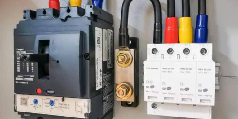
When Type 2 is mandatory
In most EV charging installations, especially commercial and fleet environments, surge protective device type 2 units at supply panels are not optional. The combination of frequent switching, high utilization, and critical uptime demands predictable surge limitation.
Residential, commercial, and fleet differences
Residential chargers often share panels with other household loads, increasing exposure to internal switching transients. Commercial installations face higher fault currents and grid interaction. Fleet charging introduces simultaneous load switching across multiple chargers, increasing internally generated disturbances. Each context reinforces the need for coordinated, panel-level protection rather than reliance on local electronics alone.
Coordinating AC and DC SPDs in Hybrid Systems

Hybrid systems combining PV generation, energy storage, and EV charging present unique coordination challenges.
AC SPDs and DC SPDs are not interchangeable. DC circuits sustain voltage continuously, while AC circuits pass through zero crossings. Devices designed for one environment may fail prematurely or behave unpredictably in the other.
Surge energy also propagates differently. In DC circuits, energy can persist longer, increasing thermal stress on components. In AC systems, energy is distributed across phases and interrupted periodically by waveform zero crossings.
Improper coordination often leads to one device absorbing more energy than intended. This results in premature degradation and false confidence in system protection. Progressive voltage limitation addresses this by ensuring each SPD stage reduces surge amplitude step by step, rather than forcing a single device to do all the work.
In hybrid systems, this means:
- DC SPDs manage array and battery-side disturbances.
- AC SPDs manage grid and load-side disturbances.
- Downstream devices only handle low-energy residuals.
Grounding, Bonding, and Surge Performance (Non-Code, Practical)
Grounding quality directly affects how well any surge protection device performs. An SPD does not eliminate surge energy. It diverts it. If the diversion path has high impedance, voltage rises elsewhere in the system.
Poor bonding between equipment enclosures, mounting structures, and grounding conductors creates uneven potential during a surge event. This uneven potential stresses insulation and electronic interfaces, even when SPDs are present.
In practical terms:
- Short, straight grounding connections improve response time.
- Consistent bonding reduces differential voltages between system components.
- SPDs cannot compensate for poorly designed grounding paths.
Focusing on grounding as part of system design, not as an afterthought, improves the effectiveness of every protective layer.
Comparison Table
| System Area | Surge Risk Type | Recommended SPD Role | SPD Type |
| PV DC Side | High DC transients | Surge diversion | DC SPD (Type 2) |
| Inverter AC Output | Switching and grid surges | Voltage clamping | AC SPD (Type 2) |
| EV Charger Supply Panel | Grid disturbances | Primary limitation | AC SPD (Type 2) |
| EV Charger Control Circuits | Low-energy residual surges | Fine protection | Type 3 SPD |
Common Design Mistakes in EV & Solar Surge Protection
One frequent mistake is relying on a single SPD to protect an entire system. This approach ignores how surge energy distributes itself across different conductors and voltages.
Another issue is neglecting DC-side protection in PV systems. Protecting only the AC output leaves the inverter exposed to array-originated transients that never reach the grid interface.
Treating EV chargers like simple loads is also problematic. Chargers actively shape power flow and generate internal switching disturbances that require upstream voltage limitation.
Finally, installing Type 3 devices without upstream protection gives a false sense of security. These devices are not designed to handle primary surge energy and will degrade quickly when misapplied.
Long-Term Reliability and Maintenance Considerations
SPDs degrade gradually. Each surge event slightly reduces their capacity to divert energy. This degradation is normal and predictable, but only if acknowledged during system planning.
EV and solar installations are expected to operate for decades. Protection strategies should include inspection intervals, status monitoring, and planned replacement based on exposure level rather than waiting for failure.
Predictable protection supports predictable uptime. This matters more in EV charging and solar generation than in many other electrical applications because downtime directly affects energy availability and operational planning.
Conclusion
EV charging systems and solar PV installations demand coordinated surge protection strategies that reflect their system topology and operating behavior. Effective use of a surge protection device depends on correct placement, coordination between AC and DC environments, and realistic expectations about performance over time.
Protection in these systems is not about absolute prevention. It is about controlling risk, limiting stress on sensitive electronics, and supporting long-term reliability through thoughtful system design.
FAQs
Related Posts