Tiếng Việt
 English
 简体中文
 Deutsch
 Español
 Français
 Italiano
 日本語
 한국어
 Polski
 Português
 Русский
 Türkçe
 Nederlands
 ไทย

An equipment manufacturer approached SignliteLED to develop a compact LED PCB board that could become a standardized lighting component across its product line.
Each finished product required six short LED boards arranged as two independent channels. Three boards in each channel needed to connect in sequence without soldering. The system also required individually addressable RGB control, a backup data path, detachable cables and mechanical mounting without adhesive.
The initial request specified WS2815 LEDs and preferred direct operation from the equipment’s existing 24V DC supply. Our technical review confirmed that the selected WS2815 solution required 12V. The customer retained the existing 24V architecture and added a dedicated 24V-to-12V power supply for the LED boards.
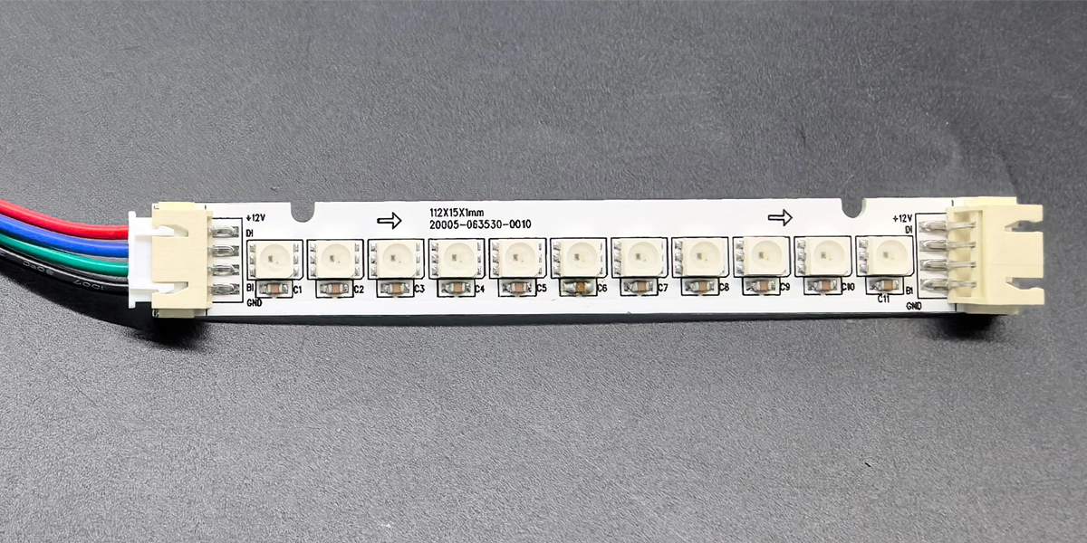
The approved custom LED PCB used 11 WS2815 LEDs, dual four-pin connectors, an aluminum substrate and two types of custom cable. The project progressed from the initial inquiry to documented finished-goods testing in approximately four weeks. After drawing approval, manufacturing, assembly and pre-shipment testing, the completed products were shipped to the customer.

The video demonstrates the completed WS2815 LED PCB system, including multi-board operation, dynamic color control and the vehicle warning-light application. The customer-specific PCB dimensions, connectors and cable arrangement are detailed in the case study below.
Tổng quan dự án
| hạng mục dự án | Final solution |
| Loại sản phẩm | Custom addressable LED PCB board |
| dắt | WS2815 addressable RGB LED |
| điện áp hoạt động | 12V DC |
| Existing equipment supply | 24V DC with a dedicated 24V-to-12V converter |
| LEDs per PCB | 11 |
| LED pitch | 7.95mm center to center |
| Overall PCB size | 112.0 × 15.0mm |
| LED layout span | 86.6mm as marked on the PCB drawing |
| Customer’s diffuser opening | Increased from 70mm to 85mm |
| PCB substrate | nhôm |
| PCB appearance | White solder mask with black silkscreen |
| Connections | Input and output connectors at opposite ends |
| tín hiệu | V+, GND, main data and backup data |
| Board-to-board cable | 300mm with connectors at both ends |
| Controller input cable | 1000mm with bare wires at one end and a PCB connector at the other |
| Mounting concept | Screws or clips rather than adhesive |
| Project status | Manufactured, tested and shipped |
Recorded Project Timeline
| cột của tiền | thời gian |
| Initial inquiry | 7-Oct-26 |
| Final drawing approval | 21-Oct-26 |
| Finished-goods test documented | 5-Nov-26 |
| Delivery status | Shipped after the pre-shipment check |
The dates describe this project’s recorded development and manufacturing process. They do not represent a standard lead time for every custom LED PCB order. Tooling, component availability, quantity and testing requirements affect each schedule.
The Customer’s Custom LED PCB Requirements
The original concept called for six LED PCB sections in each finished product. Two control channels would each operate a daisy chain of three boards.
The first request specified seven WS2815 LEDs on each PCB with approximately 10mm spacing. Every board needed one input connector and one output connector so installers could join the boards without soldering.
The project also required two cable assemblies:
- A 1000mm input cable with bare wires for the customer’s control system and a connector for the first LED PCB board
- A 300mm linking cable with connectors at both ends for joining adjacent boards
The customer’s initial wiring diagram defined the board arrangement and cable lengths before the final electrical and mechanical design had been completed.
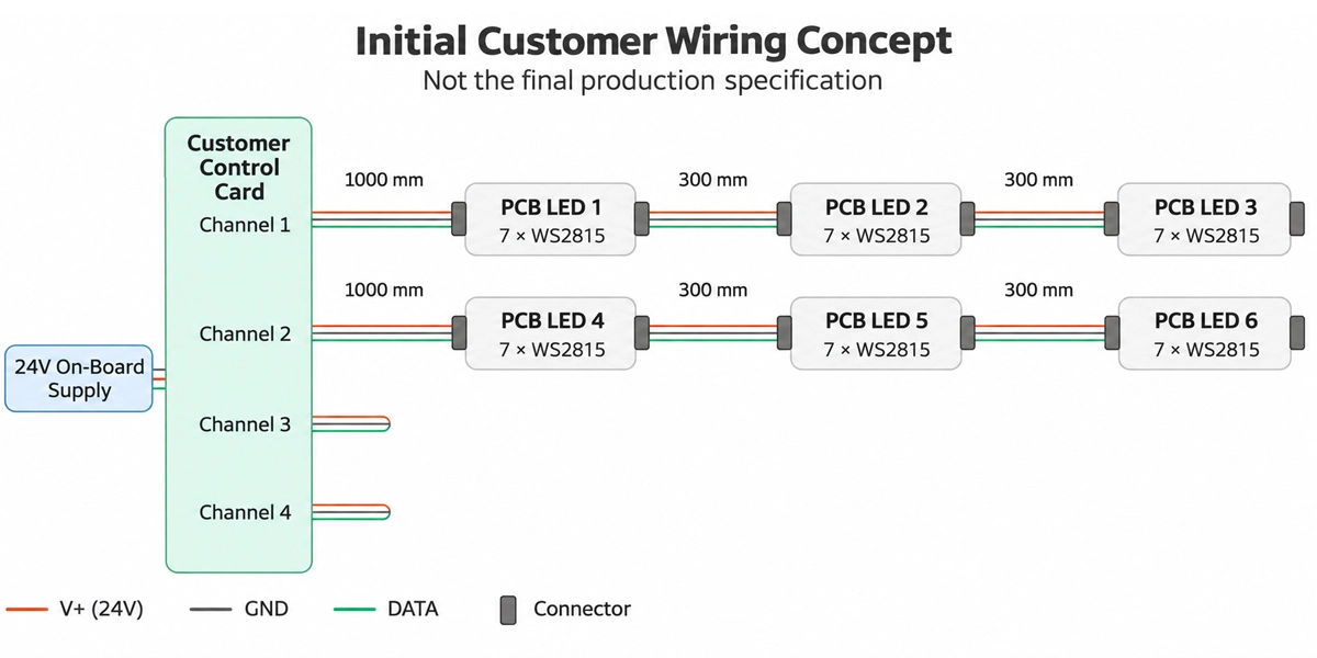
Initial customer wiring concept. The original plan used two channels with three LED PCB boards per channel, 1000mm input cables and 300mm linking cables. The voltage, LED quantity and backup-data routing were revised during engineering review.
This diagram documented the required system topology rather than the final production specification. It still showed seven LEDs per board, direct connection to the equipment’s 24V supply and three conductors for V+, GND and DATA. The final design later changed to 11 LEDs, a dedicated 12V supply and a four-conductor path that also carried the WS2815 backup-data signal.
The customer preferred WS2815 LEDs because the application required individually addressable RGB control and a backup data line. The customer also planned to secure the boards with screws or custom clips instead of adhesive tape.
A separate mechanical concept showed an initial 14mm PCB width, a 6mm proposed LED pitch, a 70mm diffuser opening and connectors at both ends. These dimensions served as the starting point for engineering review rather than approved production values.
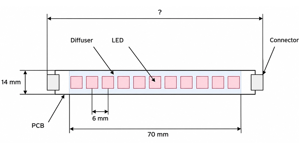
Initial mechanical concept. The proposed 14mm PCB width, 6mm LED pitch and 70mm diffuser opening were revised after the connector footprint, LED package and available installation space were reviewed.
A standard flexible LED strip or conventional sign module could not meet the required LED spacing, mechanical mounting method and connector arrangement. This application therefore required a purpose-built PCB with addressable LEDs, dual connectors and dedicated cable assemblies. Learn more about SignliteLED’s custom LED PCB design and manufacturing capabilities.
Before PCB layout began, the team needed to resolve three differences between the initial concept and a production-ready design:
- The equipment supplied 24V, while the selected WS2815 solution operated at 12V.
- The initial wiring diagram did not show the WS2815 backup-data conductor.
- The proposed LED pitch and PCB width did not provide enough space for the final LED and connector layout.
These points were addressed during the electrical and mechanical review described in the following sections.
Resolving the 24V and 12V System Difference
The equipment already contained a 24V DC supply, so the initial inquiry asked whether the WS2815 LED PCB could operate directly from 24V.
The selected WS2815 configuration operates at 12V. Connecting the equipment’s 24V supply directly to the LED boards would create an electrical mismatch. The customer instead confirmed a dedicated 24V-to-12V, 3A power supply for the lighting system.
The final power and control architecture separated the equipment supply from the LED operating voltage:
- The equipment retained its existing 24V DC architecture.
- A dedicated converter supplied 12V to the LED PCB boards.
- The customer’s control hardware supplied the addressable data signal.
- Every PCB connector carried V+, GND, main data and backup data.
This review resolved the voltage difference before PCB design and production. In a custom LED circuit board project, the equipment supply, LED operating voltage and controller interface need separate confirmation. Treating them as one specification can introduce an avoidable compatibility problem.
Developing the Production-Ready LED PCB Board
Once both parties confirmed the electrical architecture, the project moved into detailed PCB and mechanical development. Several specifications changed between the original inquiry and the approved production drawing.Increasing the Design to 11 WS2815 LEDs
Increasing the Design to 11 WS2815 LEDs
After reviewing the illuminated area and required resolution, the customer increased the LED quantity from the original minimum of seven to 11 LEDs per PCB.
The engineering layout established a 7.95mm center-to-center LED pitch. A proposed 6mm pitch left insufficient space for the selected LED packages and surrounding circuit requirements.
The approved drawing specified three separate dimensions:
- 7.95mm LED center-to-center pitch
- 112.0mm overall PCB length
- 86.6mm LED layout span
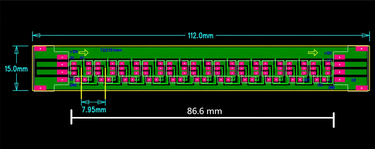
The 86.6mm value is an independently marked PCB drawing dimension. It is not the result of multiplying the LED quantity by the 7.95mm pitch.
After reviewing the drawing, the customer enlarged the equipment’s diffuser opening from 70mm to 85mm. The 85mm opening and the 86.6mm PCB layout span describe different parts of the assembly. When centered, the opening overlaps the layout span by approximately 0.8mm at each end. The customer reviewed and accepted this fit before production.
LED quantity, PCB length, optical resolution and diffuser dimensions formed one mechanical system. Changing one value affected the surrounding product design.
Expanding the PCB Width to 15mm
The original concept allowed a 14mm board width. During layout development, that width left insufficient space for the selected connectors, routing and surrounding board material.
The engineering team increased the PCB width to 15mm, and the customer confirmed that the mounting structure could accommodate the change.
A one-millimeter increase appears small, but it creates useful space on a narrow LED PCB board. Connector clearance, copper area, routing and board-edge strength all depend on the available width.
Confirming the connector footprint before production prevented an impractical terminal layout and reduced the risk of mechanical interference during installation.
Using Dual Connectors for Solderless Daisy-Chaining
Each PCB received a connector at both ends. One connector serves as the input and the other as the output. Detachable 300mm cables connect three boards into one channel.
Both connectors carry the same four electrical paths:
- V+
- GND
- Main data
- Backup data
The 1000mm input cable connects the customer’s control hardware to the first PCB. It uses bare wires at the controller end and the specified four-pin connector at the board end.
This arrangement provides several practical advantages:
- Installers can connect the LED boards without soldering inside the equipment.
- A single PCB or cable can be removed without cutting the remaining harness.
- Standardized cable lengths simplify repeat production.
- Consistent input and output connections reduce wiring variation.
- The main and backup data paths continue through the complete chain.
The PCB silkscreen and assembly documentation still need to identify input direction, output direction and pin assignment clearly. A detachable connector reduces installation work only when its orientation and wiring are unambiguous.
Similar connector positions, cable assemblies and board dimensions are available through our custom linear LED module service.
Selecting an Aluminum PCB Substrate
Thermal management entered the discussion before production. Eleven addressable RGB LEDs were concentrated on a short and narrow board, and the customer asked whether the design needed additional heat dissipation.
The customer and engineering team selected an aluminum substrate for the final PCB LED tùy chỉnh. The aluminum base spreads heat more effectively than a conventional low-power PCB structure and provides a mechanically stable foundation for screw or clip mounting.
The material choice was specific to this project. Not every WS2815 application requires an aluminum PCB. Here, LED density, compact dimensions, mounting conditions and long-term reliability supported the decision.
The visible surface used white solder mask with black silkscreen. The white surface suited the optical environment behind the diffuser, while the black markings kept connector and orientation information readable.
Routing Power and Maintaining the Backup Data Path
The customer specified that the V+ and GND paths needed enough copper capacity for a 1A design requirement. The PCB layout therefore used appropriate trace widths and copper areas for power distribution.
The completed board contained 11 WS2815 LEDs. At approximately 0.66A under an estimated full-white condition, the 1A routing target provided additional current capacity. The dedicated 3A converter also supplied headroom for the planned system arrangement.
Local decoupling capacitors were positioned close to the LEDs to stabilize the supply during changes in RGB output.
The data layout carried both the primary and backup signals from the input connector, through the LED sequence and onward to the output connector.
A backup-data LED does not create system-level redundancy by itself. The PCB traces, connectors and cables must all preserve the additional signal. In this project, all four conductors continued through the complete connection chain.
Drawing Review and Customer Approval
Production began only after the customer reviewed the main electrical and mechanical details.
| Drawing item | Approved value |
| LED type and quantity | 11 × WS2815 |
| LED pitch | 7.95mm center to center |
| Overall PCB size | 112.0 × 15.0mm |
| LED layout span | 86.6mm as marked on the PCB drawing |
| Customer’s diffuser opening | Increased from 70mm to 85mm |
| vật liệu pcb | Aluminum substrate |
| Surface appearance | White solder mask with black silkscreen |
| Connector arrangement | Four-pin input and output connectors |
| Signal paths | V+, GND, main data and backup data |
| Cable assemblies | 1000mm input cable and 300 mm board-to-board cable |
The customer accepted the 15mm board width and the fit between the 85mm diffuser opening and the 86.6mm PCB layout span. This approval established a clear production baseline for the PCB, mounting structure and surrounding optical components.
The drawing review also prevented the factory from making assumptions about the available installation space. Both parties confirmed the mechanical changes before manufacturing started.
LED PCB Assembly and Custom Cable Production
After drawing approval, the project entered PCB manufacturing, component assembly and cable production.
The LED PCB assembly process covered the aluminum boards, WS2815 LEDs, local capacitors and four-pin connectors. Production inspection also checked the white solder mask, black silkscreen, connector placement and input/output orientation.
The cables formed part of the finished assembly rather than an accessory selected after PCB production.
1000mm Controller Input Cable
The longer cable connected the customer’s control hardware to the first PCB in each channel.
One end remained as bare wires for integration with the customer’s control system. The opposite end used the selected four-pin PCB connector.
This cable carried 12V power, ground, main data and backup data to the first board.
300mm Board-to-Board Cable
The shorter cable used matching connectors at both ends. It joined the output of one PCB to the input of the next PCB, creating a detachable three-board channel.
Producing the boards and cables as one project kept the connector family, pin count and wiring sequence consistent. It also reduced the wiring work required during equipment assembly.
Pre-Shipment Testing of the LED PCB Assembly
Before packing, multiple completed boards were connected through the custom cable assemblies and powered together.
The documented test confirmed that:
- The connected PCB boards powered on.
- The LEDs illuminated.
- The board-to-board cables completed the required connections.
- Multiple PCB assemblies operated together in the planned chain.
- The connectors and visible cable assemblies followed the intended arrangement.
The test provided evidence of basic power, illumination and interconnected operation before shipment.
Its scope needs to be described accurately. The available record does not document a deliberate LED-failure test of the backup data path, a long-duration thermal qualification or operation inside the customer’s final equipment.
Those checks require separate test procedures, defined operating conditions and acceptance criteria. The phrase “tested before shipment” in this case refers to the recorded connection and lighting test, not a complete reliability certification.
Production Completed and Shipped to the Customer
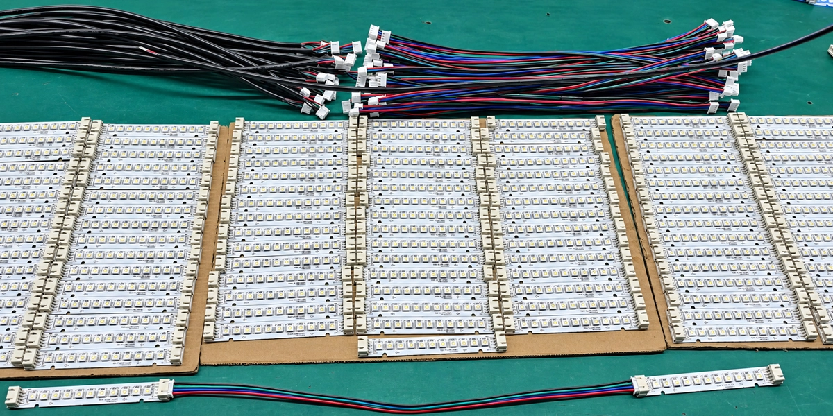
After assembly and pre-shipment testing, the finished LED PCB boards and both cable types were organized into complete sets.
The shipment included:
- Finished 12V WS2815 aluminum LED PCB boards
- 1000mm controller input cables
- 300mm board-to-board connecting cables
The products were packed and shipped to the customer. This completed the supplier-side process from inquiry and technical review through drawing approval, LED PCB assembly, cable production and pre-shipment testing.
Installation and long-term performance inside the customer’s finished equipment remain separate from the factory checks documented in this case study.
What This Custom LED PCB Project Demonstrates
| Decision point | Project response | Production result |
| 24V equipment supply versus 12V WS2815 operation | Added a dedicated 24V-to-12V, 3A power supply | Retained the equipment’s 24V architecture while supplying the LED boards correctly |
| LED quantity and illuminated area | Increased each PCB to 11 LEDs at 7.95mm pitch | Customer accepted the relationship between the PCB layout and revised diffuser opening |
| Connector size and PCB width | Increased the PCB width to 15mm and fitted connectors at both ends | Created a detachable, solderless three-board chain |
| Backup data routing | Carried V+, GND, main data and backup data through both connectors and cable types | Preserved all four electrical paths throughout the chain |
| Quản lý nhiệt | Changed the design to an aluminum substrate | Improved heat spreading and mechanical stability |
| Equipment installation | Supplied 1000mm input cables and 300mm linking cables | Reduced wiring work during equipment assembly |
| Pre-shipment verification | Connected and powered multiple finished boards | Confirmed basic illumination and interconnected operation before shipment |
The project converted an initial lighting concept into a production-ready LED PCB assembly. Electrical compatibility, mechanical dimensions, thermal management, connectors, cables and testing were resolved as parts of one system before delivery.
FAQ
To evaluate a similar LED PCB board design and assembly project, provide as much of the following information as possible:
- – Available equipment supply voltage
- – Required LED operating voltage
- – LED type or control protocol
- – LED color and addressability requirements
- – Number of LEDs per PCB
- – Preferred LED pitch
- – Maximum PCB length and width
- – PCB material preference
- – Main and backup data requirements
- – Connector model and pin assignment
- – Input and output direction
- – Cable types and lengths
- – Mounting-hole, screw or clip requirements
- – Diffuser distance and illuminated area
- – Prototype and production quantities
- – Required functional, thermal or failure tests
A wiring plan, mechanical drawing or installation-space model helps define the project efficiently. When some specifications remain open, begin with the fixed electrical, mechanical and optical limits, then develop the remaining parameters around them.
Planning a custom LED PCB project? Send the information above, together with any available drawings, wiring plans or reference samples, through Contact SignliteLED. Our team can review the electrical, mechanical, thermal and production requirements before quotation.
Bài viết liên quan