A Surge Protective Device (SPD) does not “stop lightning.” It cannot block a strike or eliminate lightning energy. What it can do is limit transient overvoltage and divert surge current into a controlled path, reducing stress on insulation and electronics. Real-world performance depends on a coordinated protection system: bonding/earthing quality, correct placement, short leads, and staged protection.
What People Mean by “Lightning Damage”

When people say “lightning damaged my equipment,” they often mix different electrical events that produce similar failures. Engineering analysis starts by separating the surge source and coupling mechanism.
1) Direct lightning strike
A direct strike injects extremely high current into a structure or line. It creates:
- Very large current magnitudes (kA range)
- Very fast rise times (microseconds)
- Large electromagnetic fields
- Severe potential differences across metalwork and wiring
This is not a “voltage spike” in the casual sense. It is a high-energy impulse that forces current through any available path, including building steel, cable shields, and power conductors.
2) Nearby/induced lightning surges
Many failures happen without a direct strike. A nearby strike can couple energy into wiring via:
- Inductive coupling (magnetic field induces voltage on loops)
- Capacitive coupling (electric field couples to conductors)
- Ground potential rise (local earth voltage shifts during the strike)
These events can produce damaging transients on power, control, and communication lines even when the utility supply remains “normal” at 50/60 Hz.
3) Switching surges
Switching operations can also create fast transients:
- Motor starts/stops
- Capacitor bank switching
- Transformer energization
- Fault clearing and reclosing
Switching surges are typically lower energy than lightning, but they can still stress sensitive electronics and insulation, and they are often repeated events (cumulative aging effect).
Myth vs Reality: Can an SPD Stop Lightning?
Below are common beliefs about SPDs and lightning, rewritten into engineering terms and corrected with system behavior.
Myth: “SPD stops lightning completely.”
Reality: An SPD does not stop lightning. It only limits transient overvoltage by providing a lower-impedance diversion path during a surge.
Engineering Explanation:
Lightning is not something you “block” with a device. A surge event forces current to flow. An SPD operates by transitioning from high impedance to low impedance when voltage rises above its threshold, then conducting surge current to a reference (typically the protective earth). The event still exists; the SPD simply changes where the energy goes and reduces the voltage seen by protected equipment.
Myth: “One SPD is enough for the whole building.”
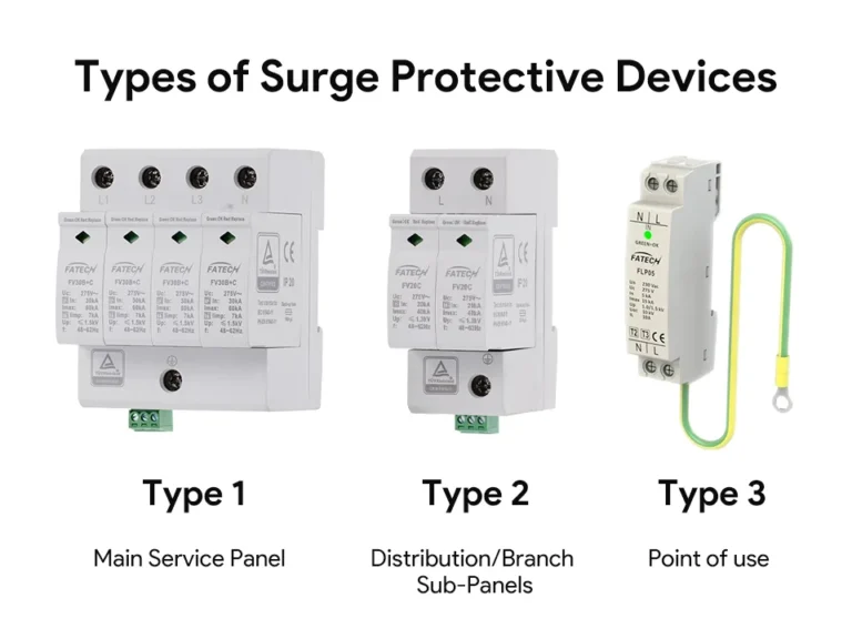
Reality: One SPD rarely provides full coverage for a facility. Effective protection is usually staged across multiple points.
Engineering Explanation:
Surge energy and fast rise times mean that wiring impedance matters. Even a few meters of conductor adds inductance that produces additional voltage (V = L × di/dt). A single SPD at the main panel may reduce incoming surges, but sensitive loads located far away can still see high let-through due to:
- cable inductance
- internal coupling between circuits
- local switching surges generated inside the building
A coordinated approach typically uses service entrance protection plus distribution and point-of-use protection where needed.
Myth: “Point-of-use protection can handle lightning alone.”
Reality: Point-of-use devices help, but they should not be treated as a substitute for upstream surge control or bonding/earthing quality.
Engineering Explanation:
A point-of-use SPD is close to the equipment, which is good for minimizing lead inductance and clamping locally. But it is limited by:
- its surge current rating
- available diversion path to earth
- the upstream impedance and system reference stability
If a large surge arrives at the facility, forcing all of it to be handled at the load end is poor coordination. The upstream network should take the bulk of the surge energy, leaving smaller residual transients for downstream stages.
Myth: “Higher rating means ‘no damage possible.’”
Reality: Higher ratings generally mean improved survivability and capability, not guaranteed zero damage.
Engineering Explanation:
SPD datasheets include ratings such as maximum discharge current, nominal discharge current, and voltage protection levels. These are standardized test conditions, not a promise that every surge is harmless. Equipment damage can still occur because:
- the surge may exceed the SPD’s capability
- installation inductance increases the effective clamping voltage
- protection is incomplete across all conductors (power, signal, ground)
- insulation coordination and equipment withstand are finite
Engineering protection is risk reduction, not absolute immunity.
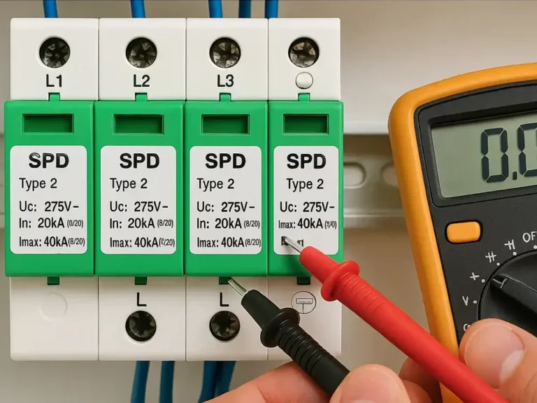
Myth: “If the indicator is ON, protection is guaranteed.”
Reality: Status indicators typically confirm basic internal condition, not the full system’s protection performance.
Engineering Explanation:
Many SPDs use thermal disconnects and indicator windows to show whether a protective element (often MOV-based) is still connected. “Green” usually means “not failed open.” It does not prove:
- correct grounding impedance
- correct installation lead length
- proper coordination with upstream/downstream devices
- that the SPD can handle the next event
An SPD can be “healthy” but installed in a way that results in high let-through voltage at the equipment terminals.
Myth: “Only lightning causes surges (switching surges don’t matter).”
Reality: Switching surges are frequent and can be a major contributor to failures and premature aging.
Engineering Explanation:
Lightning is dramatic, but switching transients are common in industrial and commercial systems. Repetitive lower-energy surges can:
- degrade MOV elements over time
- stress power supplies and insulation
- cause intermittent resets and communication faults
Ignoring switching surges often leads to protection strategies that look adequate on paper but fail in real operational environments.
What an SPD Can Do vs What It Cannot Do

What it CAN do
A Surge Protective Device can:
- Clamp transient overvoltage to a lower level than an unprotected circuit would experience
- Divert surge current away from sensitive equipment into a controlled path
- Reduce insulation stress and lower the probability of electronics failure during surge events
- Improve surge coordination when installed in layers (service entrance + distribution + local protection)
What it CANNOT do
A Surge Protective Device cannot:
- Prevent a lightning strike or “block” lightning from entering a facility
- Absorb unlimited energy (all devices have finite surge capability and aging behavior)
- Replace an external lightning protection system (air terminals, down conductors, and bonding)
- Guarantee zero damage under all surge conditions, especially for direct strike scenarios
Surge Arrester vs Surge Protective Device

The terms are often used interchangeably in casual conversation, but in engineering practice they tend to map to different installation zones and system voltages.
Where “surge arrester” is commonly used
The term surge arrester is widely used in power and utility contexts, especially medium/high voltage networks. It typically refers to devices designed to protect insulation systems in:
- distribution lines
- substations
- transformer terminals
- overhead line equipment
Why “metal oxide surge arrester” matters
A metal oxide surge arrester typically uses zinc-oxide varistor blocks (ZnO). These provide strong non-linear conduction and high energy handling compared to older gapped designs. In practical terms, a metal oxide design is the standard modern arrester approach in many HV/MV applications.
HV surge arrester vs LV surge arrester (purpose and zone)
- A HV surge arrester is installed on higher-voltage systems to protect transformers, switchgear, and line insulation from lightning and switching impulses. Its focus is insulation coordination and system-level surge control.
- A LV surge arrester (often functionally similar to an SPD in low-voltage systems) is installed at facility entrances or distribution boards to reduce transient overvoltage reaching loads.
In short: arresters are commonly associated with grid-level and transformer protection, while SPDs are commonly associated with facility-level and equipment-level protection. The physics overlaps, but the installation environment and coordination objectives differ.
Lightning Surge Path in Real Systems
Even without a direct strike to a building, lightning can still create damaging conditions due to coupling and transient behavior.
Coupling into power lines
A nearby strike can couple energy into overhead or long cable runs. The line behaves like an antenna at lightning impulse frequencies. The induced transient can propagate into the service entrance and distribution network.
Induced voltage on long conductors
Long conductors, especially when routed with separation (forming a loop area), can experience induced voltages from rapidly changing magnetic fields. This is why:
- long parallel runs
- poorly bonded cable trays
- separated earth and neutral references
can all increase surge stress.
Rise time and transient behavior
Lightning impulses rise extremely fast. Fast rise time means:
- high di/dt
- high induced voltages across inductance
- severe stress at equipment terminals
This is a key point: even if the steady-state utility voltage is perfect, equipment can fail because the damaging event is not a steady-state condition. It is a transient impulse with high-frequency content.
Why equipment fails even if utility voltage is “normal”
Most modern electronics fail due to:
- semiconductor junction breakdown
- insulation puncture in power supplies
- PCB trace arcing
- communication port damage from common-mode surges
These failures can occur when the transient exceeds component withstand for microseconds, even though RMS voltage never deviated enough to trip a breaker.
What Actually Protects Against Lightning

Lightning protection is not a single device problem. It is a system coordination problem.
1) External lightning protection
External systems provide a preferred strike termination and conduction path:
- air terminals (strike interception)
- down conductors (controlled current path)
- earth termination (current dissipation)
This reduces the chance that lightning current uses internal wiring as its path.
2) Bonding and earthing network
Bonding and earthing reduce dangerous potential differences by:
- equalizing metalwork potential
- providing low-impedance reference paths
- limiting flashover risk across gaps
Poor bonding can cause large voltage differences between “grounded” points during a surge event, which is exactly what damages equipment.
3) Surge Protective Devices at correct locations
Surge Protective Devices handle residual transients by clamping and diverting surge current. They work best when:
- installed close to the entry point of conductors
- coordinated in stages (so no single device takes everything)
- bonded to a low-impedance earth reference
4) Coordination between protection layers
Coordination means:
- upstream protection takes high-energy components
- downstream protection limits residual voltage near sensitive loads
- the earthing/bonding system provides the common reference that makes clamping meaningful
Without coordination, an SPD may conduct but still allow damaging voltage at equipment terminals due to wiring impedance and reference shifts.
Installation Reality (Why “Placement” Matters More Than “Claims”)
In surge protection, physical installation often dominates datasheet numbers. The best device can perform poorly if installed incorrectly.
Key installation principles:
- Keep leads short (long leads increase inductive voltage during fast transients)
- Use low-impedance grounding (wide conductors, short routes, solid bonding)
- Avoid loops (minimize loop area to reduce induced voltages)
- Bond metalwork properly (cable trays, enclosures, structural steel)
- Maintain correct conductor routing (reduce coupling between surge paths and sensitive circuits)
Bad installation can produce high effective let-through voltage even when the SPD itself is functioning correctly.
Comparison Table: Lightning Protection Tools vs Their Real Function
| Device/System | Primary Purpose | Direct Strike Handling | Induced Surge Handling | Notes / Limits |
| Surge Protective Device (SPD) | Clamp transient overvoltage and divert surge current on low-voltage circuits | Not designed to handle direct strike energy by itself | Effective when correctly installed and coordinated | Performance depends heavily on lead length, bonding, and coordination |
| Lightning Surge Arrester / Metal Oxide Surge Arrester | Limit impulse overvoltage on power systems using non-linear varistor behavior | Can handle high impulse currents depending on class and installation | Very effective for line/transformer impulse protection | Focus is insulation coordination; still requires proper earthing |
| HV Surge Arrester | Protect HV/MV equipment insulation (transformers, switchgear, lines) | Better suited than LV devices for high-energy events in HV zones | Effective against lightning and switching impulses | Must match system voltage and temporary overvoltage conditions |
| LV Surge Arrester | Reduce transient overvoltage in LV distribution and service entrance | Not a standalone solution for direct strike | Effective for incoming and induced surges when staged | Requires correct placement and low-impedance grounding |
| Grounding & Bonding | Provide reference stability and equalize potentials | Essential to control current paths and reduce flashover risk | Essential to reduce damaging potential differences | Not a device; poor grounding defeats protection |
Common Mistakes That Create False Protection
These are practical failure modes that make a system look protected but behave poorly during real surge events:
- Using only one SPD at the service entrance and assuming full facility protection
- Wrong placement (SPD too far from the incoming conductors or protected panel)
- No bonding coordination between electrical, structural, and telecom grounds
- Long wiring to SPD, creating high inductive let-through voltage
- Mixing wrong arrester/SPD type for the system voltage and application zone
- Ignoring signal and data lines, protecting only power conductors
- Expecting “zero damage” instead of designing for risk reduction and survivability
- No inspection/replacement planning, assuming the device never degrades
Realistic Recommendations
A neutral, engineering-focused approach is about managing risk and improving survivability:
- When lightning exposure is high, use coordinated protection (external lightning protection + bonding/earthing + staged SPDs).
- If the facility contains sensitive electronics (automation, IT, LED drivers, instrumentation), layered protection is often justified because small residual surges can still cause failure.
- Treat surge protection as part of maintenance planning: inspection, event history review, and replacement strategy matter.
- Prioritize installation quality: short leads, low impedance bonding, and correct placement often provide more benefit than chasing larger nameplate ratings.
- Consider all entry paths: power, communications, control wiring, and long outdoor cable runs are common surge entry points.
Conclusion
A Surge Protective Device does not stop lightning, and it cannot guarantee zero damage. What it can do is limit transient overvoltage and divert surge current so equipment sees less electrical stress. The real-world outcome depends on system design: bonding and earthing quality, correct placement, and coordination across protection layers. Lightning protection is a system problem, and SPDs are one important part of that system.
FAQs
Related Posts