Driven by global energy conservation, emissions reduction, and smart city development, LED street lights have become the mainstream choice for urban roadways, industrial parks, highways, and public infrastructure lighting. Compared to traditional high-pressure sodium lamps and metal halide lamps, LED street lights offer significant advantages in energy efficiency, lifespan, and intelligent light control. However, in practical engineering applications, a long-underestimated yet highly destructive risk continues to undermine the stability of LED street light systems—electrical surges and lightning surges.
Numerous engineering cases demonstrate that early failures in LED street lights are not caused by the LED chips themselves but rather by surge impacts on the power input or control systems. Consequently, surge protective devices (SPDs) have evolved from “optional configurations” to “mandatory technical components.”
This article systematically analyzes the working principles, selection criteria, installation standards, and economic value of SPDs for LED street lights from an engineering practice perspective, providing comprehensive technical guidance for lighting projects.
Why LED Street Lights Must Be Equipped with Surge Protection Devices

LED street light systems consist of LED light source modules, drivers, and control units, with core components heavily reliant on semiconductor devices. Compared to inductive light sources like traditional high-pressure sodium lamps, LED street lights employ low-voltage, high-frequency switching power supplies. This structure significantly reduces their tolerance to transient overvoltages and voltage spikes, necessitating effective surge protection capabilities.
From an environmental perspective, LED street lights operate continuously in highly exposed outdoor electrical settings. Municipal road lighting typically relies on overhead or long-distance power lines, spanning hundreds of meters or more from distribution cabinets to light poles. In regions with frequent lightning activity, these systems are highly susceptible to induced lightning energy. Even without a direct strike, intense electromagnetic fields can generate transient high voltages within power lines, which then propagate along the lines into the luminaires.
Additionally, the tall height and metallic structure of streetlight poles make them prone to energy coupling with grounding systems during thunderstorms, placing them at the forefront of surge impacts. Furthermore, road lighting systems commonly employ centralized control, where numerous lights synchronously switch on/off at sunset and sunrise. This frequent switching of high-power loads repeatedly generates switching surges in the grid, subjecting LED drivers to continuous impact.
Without surge protection, the most common failures in projects include frequent driver power supply damage, dimmed or flickering luminaires, localized LED module failures, and batch failures of luminaires along the same section. Failure analysis indicates that damage is predominantly concentrated in the power supply input stage and switching device areas, exhibiting typical surge impact characteristics.
Therefore, it can be clearly determined that the problem lies not in the LEDs themselves, but in the lack of systematic surge protection design.
In today’s outdoor operating environments, surge protection devices (SPDs) are no longer optional components for enhancing reliability. They are fundamental requirements for ensuring LED street lights achieve their designed lifespan and minimizing operational and maintenance risks.
Primary Sources of Surges in LED Street Light Systems

Surges experienced by LED street lights originate not solely from direct lightning strikes. In engineering practice, they primarily stem from the following scenarios:
- Direct lightning strikes and induced lightning: Lightning strikes can generate tens of kiloamps of current instantaneously. Even when the strike point is distant from the light pole, surges may enter the power supply lines through induction.
- Grid Operational Surges: Transformer switching, high-power equipment start/stop cycles, and reactive power compensation device operations can all generate transient overvoltages in the grid.
- Effects of Long-Distance Power Lines: Municipal street lights typically use long-distance cables for power supply. These lines act like “antennas,” making them highly susceptible to inducing lightning energy.
- Inadequate Grounding Systems: Excessively high grounding resistance or improper grounding configurations can amplify the destructive impact of surges on equipment.
How does a surge protection device work in LED street lights?
The core function of an SPD is not to “block” surges but to bypass and discharge surge energy to ground within an extremely short timeframe, thereby limiting the voltage amplitude entering the equipment.
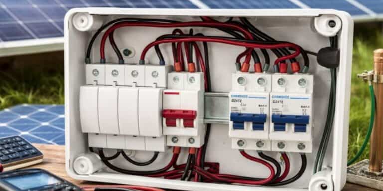
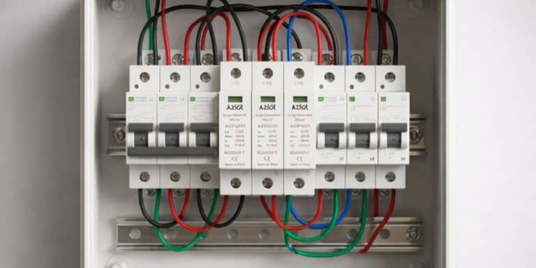
As shown in FIG 1, during normal power supply conditions, the SPD remains in a high-resistance state, equivalent to a switch being open, without affecting system operation. As shown in FIG 2, when a surge occurs (the red arrow represents a lightning surge) and the voltage exceeds the set threshold, the SPD’s internal nonlinear components rapidly conduct, equivalent to a switch closing and short-circuiting. This diverts the surge current to the grounding system, thereby protecting the downstream LED street light from damage. After the surge dissipates, the SPD automatically reverts to its high-resistance state, equivalent to the switch being open, and remains on standby.


This “instantaneous conduction and automatic recovery” operating mode makes the SPD an indispensable passive protection component in LED street light systems.
Multi-Level Surge Protection and Internal Defense Design for LED Street Lights
In high-reliability lighting projects, a single SPD is insufficient to address complex surge environments. Mature street light surge protection solutions typically employ a multi-level defense architecture:
Level 1 Protection: Installed at the distribution cabinet or base of the light pole to withstand high-energy lightning surges.


FDS20C/2-275 Class II
Designation: Type2
Classification: Class II
Protection mode: L1 , L2 , L3-PE
Nominal Voltage Un: 230/400 Vac/50(60)Hz
Max. continuous operating voltage Uc (L-N): 275 Vac/50(60)Hz
Short-circuit withstand capability: 20 kA
Continuous operating current Ic: <20 µA
Standby power consumption Pc: ≤25 mVA
Max discharge current (8/20μs) Imax: 40 kA
Nominal discharge current (8/20μs) In: 20 kA
Voltage protective level Up: ≤1.3 kV
Isolation resistance: >1000 MΩ
Housing material: UL94V-0
Degree of protection: IP20
Level 2 Protection: Positioned at the power input of luminaires to suppress residual surges.


SPD03-AC275-P/AG ClassII+III
Designation: Type2+3
Classification: Class III
Protection mode: L-N , N-PE ,L-PE
Rated input voltage Un(L-N): 230VAC, 50/60Hz
Max. continuous operating voltage Uc (L-N): 275VAC, 50/60Hz
Max discharge current (8/20μs) Imax: 6 kA
Nominal discharge current (8/20μs) In: 3 kA
Voltage protective level Up: L-N ≤1.3 kV, L(N)-PE ≤1.5 kV
Open circuit voltage Uoc: 6 kV
Backup fuse: 16A
Housing material: UL94V-0
Degree of protection: IP20
Level 3 Protection: Integrated within LED drivers or control modules for granular protection.

This tiered protection design significantly reduces the load on individual SPDs while enhancing overall system stability.
Key Technical Parameters for Selecting LED Street Light SPDs
During engineering selection, SPD technical parameters directly determine protection effectiveness, primarily including:
- Uc (Maximum Continuous Operating Voltage): Must exceed system rated voltage
- In / Imax (Nominal / Maximum Discharge Current): Reflects SPD surge energy absorption capacity
- Up (Voltage Protection Level): Lower values provide more effective equipment protection.
- Response Time: Typically required at the nanosecond level
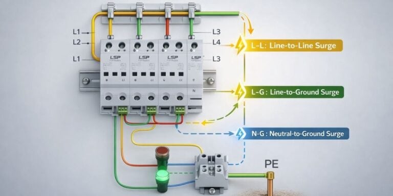
- Protection Modes: Combinations such as L-N, L-PE, N-PE, etc.
For LED street lights, a low UP value and rapid response capability are particularly critical.
Series and Parallel Connections: Choosing SPD Connection Methods

Below are two of the most common wiring diagrams for installing SPDs in streetlights, categorized as series and parallel connections:
In lighting systems, SPDs are almost exclusively connected in parallel. The advantages include:
- No impact on normal power supply to luminaires
- No lighting interruption if the SPD fails
- Easier installation and maintenance
- While series connection theoretically limits current, it is rarely used in streetlight systems and is reserved for specific power supply designs.
Differences Between AC SPD and DC SPD
The core distinction between SPD and DC SPD lies in the different types of currents they protect, which directly determines their operating principles, failure modes, and application scenarios. Simply put, AC SPD is used in AC systems, while DC SPD is specifically designed for DC systems.
A statistical table of the differences between AC SPD and DC SPD
| Comparison Dimension | Alternating Current (AC), direction changes periodically | Direct Current (DC), direction remains constant |
| Current Type | Alternating Current (AC), direction changes periodically | Direct Current (DC), direction remains constant |
| Working Principle | Uses the natural zero-crossing point of AC to extinguish arcs, commonly uses MOV, GDT | No natural zero-crossing point, requires multi-stage TVS or gap arc extinguishing, relies on active cutoff circuits |
| Core Components | MOV (Metal Oxide Varistor), GDT (Gas Discharge Tube) | Multi-stage MOV series connection, TVS diode, active circuit breaker device |
| Residual Voltage Level | Typically 1.5–2.5 kV | Typically ≤1.5 kV (requires lower voltage to protect sensitive electronic equipment) |
| Failure Mode | MOV degradation leads to increased leakage current, thermal trip automatically disconnects | High risk of continuous arc, prone to short circuits, requires external DC MCCB backup protection |
| Typical Application Scenarios | Building distribution boxes, UPS input ends, household socket circuits | Photovoltaic combiner boxes, DC charging piles, energy storage systems, electric vehicle DC bus lines |
| Rated Voltage (Uc) | Common 385V AC, 440V AC | Common 600V DC, 1000V DC, 1500V DC (need to reserve 20% margin) |
| Polarity Requirement | No need to distinguish positive and negative poles (AC has no polarity) | Must match positive and negative poles (+/-), reverse connection may lead to failure |
| PID Effect Impact | None | Need to consider Potential Induced Degradation (PID), especially in high-voltage photovoltaic systems |
| Grounding Requirements | Grounding resistance ≤1Ω (important places) | Grounding is equally important, but more attention is paid to loop impedance and equipotential connection |
| Standard Basis | IEC 61643-11, | IEC 61643-31 |
- Operating Principle and Circuit Structure: AC SPDs utilize the natural arc extinction at the zero-crossing point of AC current, employing MOVs or GDTs. They require compatibility with multi-mode protection for L, N, and PE lines and incorporate thermal trip mechanisms. DC SPDs lack a zero-crossing point, necessitating bidirectional TVS or multi-stage gap arc extinction. They use series-connected multi-stage MOVs to reduce residual voltage and feature active shutdown circuits.
- Failure Mode Differences: AC SPD failure manifests as increased leakage current, automatically isolated via thermal tripping. DC SPDs, prone to sustained short circuits due to difficult arc extinction, require dedicated DC MCCB backup protection.
- Application Scenarios: AC SPDs are used in AC systems such as building distribution panels and terminal equipment. DC SPDs are used in photovoltaic systems, charging stations, and new energy DC busbars. For example, photovoltaic combiner boxes require 1000 VDC SPDs, while the AC side of inverters requires 385 VAC SPDs.
- Selection: AC SPDs require current-carrying capacity based on building classification, with ground resistance ≤1Ω. DC SPDs must match maximum continuous operating voltage and polarity, accounting for PID effects—e.g., a 1000V system requires a 1200 VDC SPD.
How to Select Appropriate Surge Protective Devices for Street Light Projects
When choosing SPDs for engineering projects, the following factors should be comprehensively considered:
- Lightning density at the project location
- Pole height and distribution density
- Individual lamp power and total system load
- Presence of intelligent control and communication modules
For high-risk lightning areas or critical roadways, SPD products with a discharge capacity of no less than 10 kA–20 kA are recommended.
Best Installation Practices for Surge Protection Devices in LED Street Lights
Even with high-performance SPDs, improper installation can significantly reduce protection effectiveness. Engineering practices should adhere to these principles:
- Minimize distance between SPD and protected equipment.
- Ensure grounding wires are “short, straight, and thick.”
- Avoid forming loops or unnecessary bends.
- Regularly inspect SPD failure indicators.
- Proper installation practices often yield greater practical benefits than merely increasing SPD parameters.
Economic Benefits of Surge Protection Devices in LED Street Lights
While SPDs increase initial material costs, their economic advantages are substantial when evaluated over the entire lifecycle:
- Significantly reduces LED street light failure rates
- Decreases maintenance and replacement frequency
- Prevents large-scale repairs and customer complaints
- Enhances overall project reliability and brand reputation
In most municipal projects, SPD costs typically account for less than 1% of total lighting system expenses while reducing failure risks by over 30%.
Common Misconceptions in LED Street Light SPD Applications
The following issues are particularly prevalent in actual projects:
- Mismatched SPD voltage rating selection
- Neglecting grounding system quality
- Excessive distance between SPD and load
- Focusing solely on AC protection while ignoring DC protection
- These errors often render SPDs ineffective, preventing them from delivering proper protection.
Conclusion
As LED street lights evolve toward higher power, intelligence, and system integration, demands for electrical safety and stability continue to rise. Surge protection devices are no longer optional extras but essential technical foundations for ensuring long-term reliable operation of LED street lights.
Through scientific SPD selection, rational protection architecture, and standardized installation, lighting projects can not only effectively reduce failure rates but also significantly enhance overall project value and market competitiveness. For LED street light projects pursuing long-term stable operation, surge protection has become an indispensable critical component.
FAQs
Related Posts