Polski
  English
  简体中文
简体中文  Deutsch
  Español
  Français
  Italiano
  日本語
日本語  한국어
한국어  Português
  Русский
  Türkçe
  Nederlands
  Tiếng Việt
  ไทย
ไทย 
Ponieważ produkty oświetleniowe wciąż się kurczą, przestrzeń instalacyjna stała się jednym z największych ograniczeń projektowych. Ultra cienkie światła LED pasują to wyzwanie, zmniejszając szerokość płytki drukowanej przy jednoczesnym zachowaniu ciągłego, bezkropkowego oświetlenia dzięki technologii COB. W porównaniu z konwencjonalnymi taśmami LED pasują do znacznie węższych rowków, profili aluminiowych, detali mebli, gablot i elementów architektonicznych, w których nie można ukryć standardowych listew.
Zmniejszenie szerokości PCB wpływa jednak znacznie bardziej niż wymiary fizyczne. Węższa płytka drukowana zmienia pojemność prądu, rozpraszanie ciepła, wytrzymałość mechaniczną, charakterystykę spadku napięcia i tolerancję instalacji. Najmniejszy pasek nie zawsze jest zatem najlepszym wyborem. Każdy projekt wymaga zrównoważenia dostępnej przestrzeni, wydajności oświetlenia, niezawodności i długoterminowych warunków pracy.
W tym artykule wyjaśniono, jak bardzo cienkie Taśmy LED COB Osiągnij swoją kompaktową formę, jakie są dostępne praktyczne opcje szerokości, gdzie każdy rozmiar jest najbardziej odpowiedni i jakie czynniki projektowe wpływają na jakość instalacji i żywotność. Niezależnie od tego, czy określasz oświetlenie mebli, ekspozycji detalicznych, detale architektoniczne czy precyzyjne aplikacje, poniższe sekcje zapewniają praktyczne ramy do wyboru odpowiedniej szerokości paska i unikania typowych błędów projektowych.
Czym są ultra cienkie światła taśmowe LED?
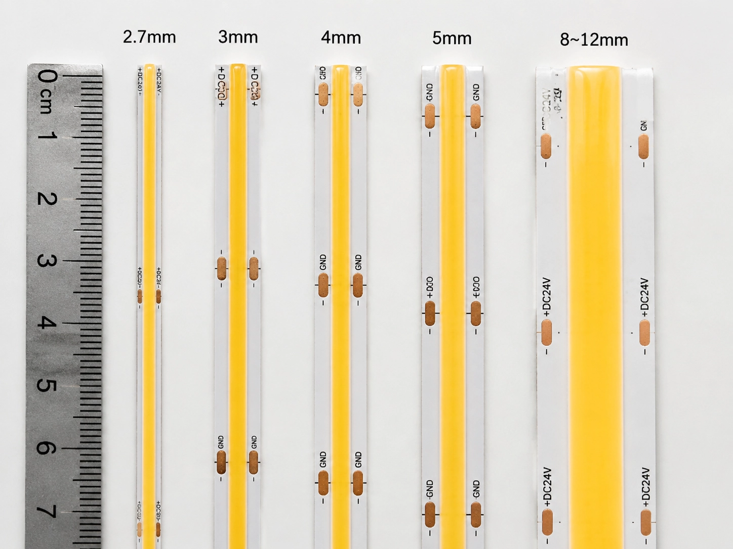
Ultra Thin Strip LED Lights to kompaktowe systemy oświetlenia LED oparte na technologii COB (chip-on-board), zaprojektowane z ultrawąskich płytek drukowanych, zwykle o szerokości od 2,7 mm do 5 mm. Są one opracowane dla instalacji o ograniczonej przestrzeni kosmicznej, w których standardowe taśmy LED nie pasują, a jednocześnie zapewniają ciągłe oświetlenie bez kropek.
Ultra cienkie światła LED paski są definiowane przede wszystkim przez szerokość PCB, a nie fizyczną grubość taśmy. W porównaniu z konwencjonalnymi taśmami LED, które zazwyczaj wykorzystują płytki drukowane o średnicy 8–12 mm, ultracienkie konstrukcje COB zmniejszają szerokość płytki drukowanej, aby pasowały do wąskich kanałów, detali mebli, gablot, oświetlenia wpuszczanego i aplikacji architektonicznych, w których wymagana jest instalacja ukryta.
Technologia COB (Chip-on-board) umożliwia ultracienkie konstrukcje poprzez montowanie chipów LED bezpośrednio na płytce drukowanej zamiast korzystania z pojedynczych pakietów LED. Ta kompaktowa konstrukcja zmniejsza ślad optyczny, zwiększa gęstość LED i umożliwia ciągłą powłokę fosforową, tworząc bezszwową powierzchnię emitującą światło z jednorodnym, bezkropkowym oświetleniem. Jednak zmniejszenie szerokości PCB powoduje również kompromisy inżynieryjne. Węższa płytka drukowana zawiera mniej miedzi do przenoszenia prądu i rozpraszania ciepła, co może wpływać na spadek napięcia, wydajność termiczną, maksymalną długość instalacji i niezawodność mechaniczną. Dlatego najlepsza ultracienka taśma LED nie zawsze jest najwęższą dostępną opcją, ale najwęższą konstrukcją, która spełnia wymagania oświetlenia projektu, pojemność elektryczną, warunki cieplne i długoterminowe potrzeby w zakresie niezawodności.
Ultra cienki przewodnik po taśmie LED
| Szerokość płytki drukowanej | Kategoria | Najlepsze aplikacje | Powód wyboru |
| 2,7 mm | pasek mikro cob | Wnętrza motoryzacyjne, precyzyjne instalacje oświetleniowe | Maksymalne ukrycie dla bardzo ograniczonej przestrzeni |
| 3 mm | Ultra wąski pasek kolby | Wyświetlacze biżuterii, miniaturowe szafki, wnętrza premium | Najmniejszy praktyczny profesjonalny ślad instalacji |
| 4 mm | Ultra cienki pasek kolby | Meble, Szafy, Millwork, Projekty mieszkaniowe | Najlepsza równowaga między kompaktowym rozmiarem a niezawodnością |
| 5mm | Smukły pasek kolby | Wyświetlacze detaliczne, oświetlenie architektoniczne, aplikacje o dłuższym działaniu | Lepsza wydajność termiczna i stabilność elektr |
| 8–12 mm | Standardowa taśma LED (SMD i COB) | Ogólne oświetlenie mieszkalne i komercyjne | Wyższy margines wydajności i łatwiejsza integracja |
Kluczowe wynos
Ultra cienkie światła LED dobierane są na podstawie równowagi między przestrzenią instalacyjną, wydajnością oświetlenia i długotrwałą niezawodnością. Węższe płytki drukowane zapewniają lepsze ukrycie i większą elastyczność instalacji, ale także zmniejszają marginesy elektryczne i termiczne. Optymalnym wyborem jest najwęższa szerokość płytki drukowanej, która może utrzymać stabilne oświetlenie, prawidłowe zarządzanie ciepłem i niezawodne działanie w celu zamierzonego zastosowania.
W jaki sposób technologia COB sprawia, że paski LED są ultra cienkie?
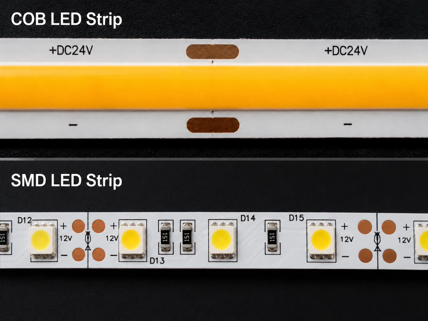
Technologia COB (Chip-on-board) umożliwia ultracienkie projekty taśm LED, zmieniając sposób rozmieszczania chipów LED na płytce drukowanej. Zamiast korzystać z indywidualnych pakietów LED SMD, technologia COB montuje gołe chipy LED bezpośrednio na płytce drukowanej, usuwając dodatkową przestrzeń wymaganą przez tradycyjne opakowania LED.
Ten kompaktowy układ chipowy zwiększa gęstość LED, zmniejsza ślad optyczny i umożliwia producentom opracowanie ultrawąskich projektów PCB o szerokości od 2,7 mm do 5 mm przy zachowaniu ciągłego, bezkropkowego oświetlenia.
Kluczowe na wynos
- Bezpośredni montaż chipowy zmniejsza przestrzeń w opakowaniu: COB umieszcza chipy LED bezpośrednio na płytce drukowanej, eliminując większe pojedyncze pakiety LED używane w tradycyjnych paskach SMD. To jest główny powód, dla którego paski COB mogą osiągnąć węższe szerokości PCB.
- Wyższa gęstość wiórów zapewnia ciągłe oświetlenie: dzięki umieszczeniu chipów bliżej siebie, technologia COB umożliwia powłoce fosforowej wtapianie poszczególnych źródeł światła w jednolitą powierzchnię bez widocznych kropek LED.
- Zmniejszona powierzchnia optyczna poprawia elastyczność instalacji: technologia COB minimalizuje obszar emitujący światło, umożliwiając dopasowanie pasków LED do wąskich kanałów, detali mebli, gabw i ukrytych konstrukcji oświetleniowych.
- Ultracienkie konstrukcje wymagają dodatkowej kontroli inżynieryjnej: w miarę jak szerokość płytek drukowanych maleje, rozsiewanie termiczne i pojemność elektryczna stają się bardziej ograniczone. Kompaktowe projekty COB wymagają starannej optymalizacji układu chipów, struktury PCB, rozpraszania ciepła i zarządzania energią.
W przeciwieństwie do konwencjonalnych pasków LED SMD, gdzie każda zapakowana dioda LED zajmuje dodatkową przestrzeń do montażu, paski LED COB umieszczają gołe chipy LED bezpośrednio na płytce drukowanej. Usuwając odstępy między pakietami, producenci mogą zwiększyć gęstość wiórów i zmniejszyć ogólną szerokość płytki drukowanej.
Proces ten polega na czymś więcej niż tylko zmniejszeniu płytki drukowanej. Osiągnięcie ultrawąskiej taśmy LED COB wymaga skoordynowanej optymalizacji opakowania półprzewodnikowego, układu PCB, odstępów między wiórami, projektowania optycznego, rozpraszania ciepła i precyzji produkcji. Każdy czynnik wpływa na równowagę między kompaktowymi wymiarami, świetlną wydajnością, niezawodnością i długoterminową stabilnością działania.
1. Bezpośredni montaż chipa
Bezpośredni montaż chipowy jest głównym powodem, dla którego taśmy LED COB mogą osiągnąć znacznie węższe szerokości PCB niż tradycyjne paski SMD. Bez pojedynczych pakietów LED zajmujących przestrzeń na desce, producenci mogą pozycjonować chipy znacznie bliżej siebie, tworząc ciągłą linię światła, jednocześnie zmniejszając widoczne luki w jaskrawości. Ta wyższa integracja poprawia również spójność oświetlenia, gdy listwa jest zainstalowana w pobliżu oświetlonej powierzchni.
2. Ciągła powłoka fosforowa
Ciągła warstwa fosforowa pokrywa gęsto ułożone wióry LED i miesza światło emitowane z pojedynczych matryc w jedną, jednolitą, świetlistą powierzchnię. Rezultatem jest płynne, bezkropkowe oświetlenie bez widocznych gorących punktów LED. Ta cecha optyczna jest szczególnie cenna w zastosowaniach takich jak oświetlenie mebli, wyświetlacze biżuterii, półki handlowe i detale architektoniczne, gdzie źródło światła jest często widoczne z bliskiej odległości oglądania, a jednorodność wizualna jest niezbędna.
3. Mniejszy ślad optyczny
Łącząc bezpośrednie mocowanie wiórów z ciągłą emisją światła, technologia COB zmniejsza ślad widzialny przy zachowaniu wysokiej jakości optyki. Umożliwia to instalację wewnątrz wąskich rowków, smukłe profile aluminiowe, ukryte kanały i kompaktowe konstrukcje oświetleniowe, w których konwencjonalne taśmy LED nie mogą osiągnąć tego samego efektu wizualnego.
Zmniejszona szerokość płytki drukowanej wprowadza jednak również kompromisy inżynierskie. Węższa płytka drukowana zawiera mniej miedzi do przenoszenia prądu i rozpraszania ciepła, co sprawia, że spadek napięcia, wydajność termiczna i maksymalna długość pracy są bardziej krytyczne względy projektowe. Z tego powodu udane ultracienkie instalacje taśm LED COB zależą nie tylko od kompaktowych wymiarów, ale także od odpowiedniego rozsyłu mocy, zarządzania termicznego i metod instalacji.
| Czynnik inżynierski | Przewaga kolby | Wpływ projektu |
| Struktura chipa | Bezpośredni montaż chipa | Umożliwia węższe projekty PCB |
| strujka świetl | Ciągła powłoka fosforowa | Tworzy bezproblemowe, bezkropkowe oświetlenie |
| Odcisk optyczny | Zmniejszony odstęp między komponentami | Pasuje do ukrytych i kompaktowych instalacji |
| Szerokość płytki drukowanej | Układy 2,7–5 mm | Wymaga starannego planowania elektrycznego i termicznego |
klucz kluczowy
Technologia COB umożliwia ultracienkie paski LED dzięki połączeniu bezpośredniego montażu w chipie, ciągłej powłoki fosforowej i kompaktowej struktury optycznej. Chociaż te innowacje umożliwiają węższe szerokości płytek drukowanych i lepszą integrację wizualną, zmniejszają również marginesy elektryczne i termiczne. Skuteczne projekty zależą zatem od wyważenia kompaktowych rozmiarów z dostarczaniem mocy, rozpraszaniem ciepła i długoterminową niezawodnością, a nie na minimalizacji szerokości płyty drukowanej.

Dlaczego szerokość płytki drukowanej jest ograniczona w ultracienkich taśmach LED COB?
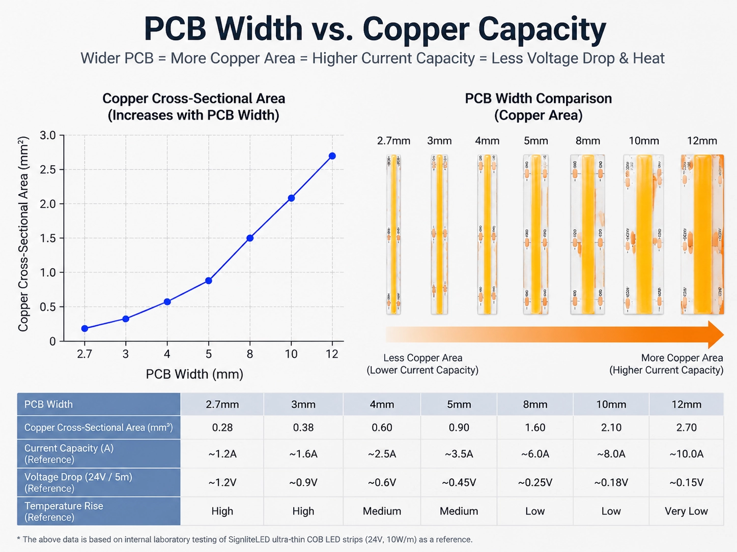
Szerokość płytki drukowanej jest ograniczona w ultracienkich taśmach LED COB, ponieważ zmniejszenie płytki drukowanej zmniejsza również powierzchnię miedzi, pojemność prądową, odprowadzanie ciepła i wytrzymałość mechaniczną. Te ograniczenia inżynieryjne określają, jak wąska może być taśma LED COB, przy jednoczesnym zachowaniu niezawodnej wydajności. Najlepsza konstrukcja jest zatem najwęższą płytką drukowaną, która nadal spełnia wymagania elektryczne, termiczne i mechaniczne.
Dlaczego wąska płytka drukowana zwiększa spadek napięcia?
Wąska płytka drukowana zwiększa spadek napięcia, ponieważ zawiera mniej miedzi do przenoszenia prądu elektrycznego. Wynikowy wzrost oporu elektrycznego zmniejsza przepustowość prądu i ogranicza niezawodną długość taśmy. W ultracienkich listwach LED COB węższe płytki drukowane zawierają mniej przewodzące materiały, co zwiększa opór elektryczny i zmniejsza przenoszenie prądu.
Może to prowadzić do kilku wyzwań inżynieryjnych:
- Wyższy spadek napięcia: Dłuższe instalacje mogą odczuwać zmniejszenie jasności pod koniec paska.
- Niższa tolerancja mocy: Wąskie płytki drukowane mają mniejszy margines na pracę z wysokim prądem.
- Krótsze ciągi ciągłe: Maksymalna długość instalacji jest często zmniejszana w porównaniu z szerszymi taśmami LED.
Z tego powodu planowanie zasilania ma kluczowe znaczenie przy wyborze ultracienkich pasków LED COB. Czynniki takie jak napięcie robocze, zużycie energii na metr, długość paska i pojemność sterownika powinny być oceniane przed instalacją.
Systemy 24V zmniejszają prąd o połowę w porównaniu z 12 V dla tej samej mocy wyjściowej, co zmniejsza spadek napięcia i obsługuje dłuższe ciągłe ciągi w ultracienkich instalacjach COB. Jednak rzeczywista wydajność nadal zależy od konstrukcji PCB, gęstości mocy i warunków instalacji. Dla odniesienia, ten przewodnik wyjaśnia Jak długo taśma LED COB 24V może działać bez wtrysku zasilania? oraz czynniki wpływające na maksymalną długość przebiegu.
Dlaczego wąska płytka drukowana rozprasza ciepło mniej wydajnie?
Wąska płytka drukowana rozprasza ciepło mniej wydajnie, ponieważ ma mniejszą powierzchnię miedzi, aby rozprowadzać ciepło z chipów LED. Wraz ze wzrostem temperatury roboczej, efektywne zarządzanie termiczne staje się coraz ważniejsze dla utrzymania wydajności LED i żywotności. Warstwa miedzi PCB nie tylko przenosi prąd elektryczny, ale także pomaga rozprowadzać ciepło wytwarzane przez chipy LED.
Gdy szerokość PCB zmniejsza się, dostępna powierzchnia miedzi zmniejsza się, zmniejszając naturalną ścieżkę termiczną. To sprawia, że zewnętrzne zarządzanie ciepłem staje się coraz ważniejsze, szczególnie w przypadku aplikacji o wysokiej jasności lub instalacji o długich godzinach pracy.
Ultracienkie paski LED COB często wymagają profili aluminiowych, ponieważ zapewniają:
- Ulepszone przenoszenie ciepła z dala od chipów LED
- Bardziej stabilna temperatura pracy
- Ochrona przed przegrzaniem w zamkniętych pomieszczeniach
- Lepsza długoterminowa niezawodność LED
Bez wystarczającego zarządzania termicznego nadmierne ciepło może zmniejszyć wydajność LED, przyspieszyć starzenie materiału i skrócić żywotność systemu oświetleniowego.
Dlaczego ultra-wąskie płytki drukowane są trudniejsze do wyprodukowania?
Ultra-wąskie płytki PCB są trudniejsze do wyprodukowania, ponieważ mniejsze miedziane podkładki i węższe konstrukcje zmniejszają wytrzymałość mechaniczną i zwiększają tolerancje produkcyjne. Węższa płytka drukowana ma mniejsze podparcie fizyczne i mniejsze obszary połączeń, co czyni go bardziej wrażliwym na naprężenie zginające, wyrównanie złączy i obsługę instalacji.
Ważne kwestie to:
- Minimalny promień gięcia
- Zgodność złącza
- Jakość lutowania
- Elastyczność i trwałość PCB
- Spójność produkcji
Niezwykle wąskie projekty PCB wymagają precyzyjnej kontroli produkcji, ponieważ niewielkie zmiany mogą wpływać na wydajność elektryczną i niezawodność instalacji.
Kluczowa zasada projektowania
Minimalna praktyczna szerokość płytki drukowanej jest określana przez redukcję rozmiaru z wyważeniem z wymaganiami inżynieryjnymi. Ultracienkie paski LED COB zapewniają doskonałe ukrycie, ale ich wydajność zależy od odpowiedniego planowania elektrycznego, projektowania termicznego i metod instalacji.
Wybór najmniejszej płytki drukowanej nie zawsze jest najlepszym rozwiązaniem. Optymalna szerokość to ta, która zapewnia wystarczającą pojemność elektryczną, stabilność termiczną i niezawodność mechaniczną dla zamierzonego zastosowania.
Jak wybrać odpowiednią szerokość płytki drukowanej?
Wybór odpowiedniej szerokości płytki drukowanej dla ultracienkiej taśmy LED COB wymaga zrównoważenia przestrzeni montażowej, wydajności elektrycznej, zarządzania termicznego i długoterminowej niezawodności. Najwęższy dostępny PCB nie zawsze jest najlepszym wyborem. Idealna szerokość to najmniejsza konstrukcja, która może spełnić wymagania oświetleniowe projektu przy zachowaniu wystarczających marginesów wydajności.
Szerokość PCB bezpośrednio wpływa na rozmiar fizyczny paska LED, ale wpływa również na pojemność miedzi, spadek napięcia, rozpraszanie ciepła i wytrzymałość mechaniczną. Profesjonalne projektowanie oświetlenia powinno zatem uwzględniać zarówno widoczne wymagania instalacyjne, jak i ograniczenia techniczne każdego rozmiaru płytki drukowanej.
Pasek LED COB 2,7 mm: maksymalna miniaturyzacja
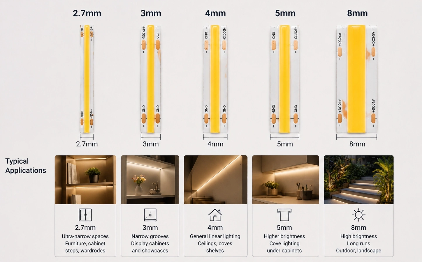
Pasek LED COB 2,7 mm jest najwęższą dostępną w handlu szerokością, stosowaną do oświetlenia wnętrz samochodowych i precyzyjnych konstrukcji wyświetlacza, w których nawet pasek 3 mm nie zmieści się”. Jego główną zaletą jest możliwość dopasowania się do bardzo ograniczonych przestrzeni, w których nie można zainstalować nawet nieco szerszych taśm LED.
Typowe zastosowania to:
- Precyzyjne struktury wyświetlacz
- Szczegóły wnętrza motoryzacyjnego
- Miniaturowe systemy oświetlenia
- Wysoce ukryte instalacje dekoracyjne
Niezwykle wąska płytka drukowana zapewnia maksymalną elastyczność instalacji, ale także zapewnia najniższy margines elektryczny i termiczny. Przy mniejszej dostępnej powierzchni miedzi projektanci muszą zwracać większą uwagę na pojemność prądową, spadek napięcia i rozpraszanie ciepła.
Pasek LED COB 2,7 mm najlepiej wybrać, gdy głównym problemem są ograniczenia miejsca, a nie maksymalna jasność lub długa praca ciągła.
Pasek LED COB 3 mm: ultra-wąskie rozwiązanie profesjonalne
Pasek LED 3 mm COB jest najczęściej stosowaną ultra-wąską szerokością do ekspozycji biżuterii i szklanych szafek, oferując prawie niewidzialne ukrycie o lepszej stabilności mechanicznej niż 2,7 mm. Jest to jeden z najpopularniejszych wyborów w aplikacjach, w których źródło światła musi pozostać prawie niewidoczne, przy jednoczesnym zachowaniu niezawodnej wydajności.
Typowe aplikacje obejmują:
- Wyświetlacze biżuterii
- Szafki szklane
- Szczegóły mebli premium
- Małe elementy oświetlenia architektonicznego
W porównaniu z konstrukcjami 2,7 mm, taśmy LED COB 3 mm zapewniają nieco lepszą stabilność elektryczną i mechaniczną, przy jednoczesnym zachowaniu bardzo małej powierzchni instalacyjnej.
W przypadku projektów oświetlenia precyzyjnego 3 mm jest często preferowanym wyborem, gdy ukrywanie i jakość wizualna są ważniejsze niż maksymalna moc.

Pasek LED COB 4 mm: najlepsza równowaga między rozmiarem a niezawodnością
Pasek LED 4 mm COB to standardowy wybór do oświetlenia szafek i mebli, równoważenie miedzianej pojemności z płytką miedzianą z krytym śladem. Zapewnia wystarczającą powierzchnię PCB dla lepszej pojemności miedzi, lepszej wydajności termicznej i silniejszej niezawodności mechanicznej, a jednocześnie nadaje się do instalacji ukrytych.
Szerokość ta jest powszechnie używana do:
- Oświetlenie szafki
- Integracja mebli
- Dekoracja wnętrz
- Projekty mieszkaniowe premium
W porównaniu z węższymi opcjami, konstrukcje 4 mm zapewniają większą tolerancję na spadek napięcia, przegrzanie i zmienność instalacji. W przypadku wielu profesjonalnych zastosowań ta szerokość zapewnia najlepszą kombinację wyglądu, wydajności i niezawodności.
Pasek LED COB 5 mm: zorientowany na wydajność smukły design
Pasek LED 5 mm COB to najszersza opcja ultracienka, używana do ekspozycji detalicznych i oświetlenia architektonicznego, które wymagają dłuższych ciągłych przebiegów i wyższego prądu.
Szersza struktura PCB pozwala na:
- Lepsze prowadzenie bieżącej obsługi
- Poprawiono dystrybucję ciepła
- Bardziej niezawodna długotrwała praca
- Łatwiejsza kompatybilność instalacji
Paski LED COB 5 mm są powszechnie wybierane do ekspozycji detalicznych, oświetlenia komercyjnego, zastosowań architektonicznych i projektów wymagających dłuższych godzin pracy.
Chociaż wymagają nieco więcej miejsca na montaż, ich zwiększony margines inżynieryjny sprawia, że są odpowiednie do środowisk, w których niezawodność jest ważniejsza niż osiągnięcie jak najmniejszego śladu.
Przewodnik wyboru szerokości PCB dla ultracienkich taśm LED COB
| Szerokość płytki drukowanej | Kategoria projektu | Główna przewaga | Typowe zastosowania | Rozważanie inżynieryjne |
| 2,7 mm | Ekstremalna miniaturyzacja | Maksymalne ukrycie w ograniczonych przestrzeniach | Precyzyjne wyświetlacze, kompaktowe oświetlenie | Najniższy margines termiczny i elektryczny; wymaga starannej konstrukcji systemu |
| 3 mm | Ultra-wąski projekt kolby | Najmniejszy praktyczny profesjonalny ślad instalacji | Wyświetlacze biżuterii, detale mebli, wnętrza premium | Wymaga uwagi na dystrybucję mocy i zarządzanie ciepłem |
| 4 mm | Zrównoważony ultra-cienki design | Najlepsza równowaga między rozmiarem a niezawodnością | Szafki, meble, detale architektoniczne | Nadaje się do większości ukrytych projektów oświetleniowych |
| 5mm | Smukły design zorientowany na wydajność | Poprawiona stabilność termiczna i | Oświetlenie handlowe, komercyjne, długotrwałe | Lepszy wybór, gdy niezawodność jest priorytetem |
| 8mm-10mm | Standardowa taśma LED COB (asortyment produktów COB) | Wyższy margines wydajności i łatwiejsza integracja | Oświetlenie wielkopowierzchniowe, ogólne zastosowania | Wymaga większej przestrzeni instalacyjnej, ale zapewnia większą pojemność |
Zasada wyboru
Prawidłowa szerokość płytki drukowanej zależy od zależności między ograniczeniami instalacyjnymi a wymaganiami systemowymi. Wybierz paski LED COB 2,7 mm–3 mm, gdy priorytetem jest maksymalne ukrycie, projekty 4 mm przy równoważeniu wyglądu i niezawodności oraz wersje 5 mm, gdy wymagana jest lepsza wydajność termiczna i dłuższa praca.
Celem ultracienkiej konstrukcji taśmowej LED COB jest nie tylko zmniejszenie rozmiaru płytki drukowanej, ale osiągnięcie najlepszej kombinacji kompaktowej instalacji, stabilnego oświetlenia i długotrwałej niezawodności.
Gdzie są używane ultracienkie paski LED COB?
Ultracienkie taśmy LED COB są używane głównie w aplikacjach, w których przestrzeń instalacyjna jest ograniczona, ale wymagane jest ciągłe oświetlenie bez kropek. Ich wąska konstrukcja PCB sprawia, że idealnie nadają się do ukrytego oświetlenia, precyzyjnych wyświetlaczy, integracji mebli i detali architektonicznych, w których standardowe paski LED nie pasują.
Główną zaletą ultracienkich taśm LED COB nie jest po prostu ich mniejszy rozmiar, ale ich zdolność do zapewnienia profesjonalnego oświetlenia w ograniczonych przestrzeniach. Łącząc technologię COB z ultra-wąskimi projektami PCB, te paski LED umożliwiają bezproblemowe oświetlenie przy zachowaniu czystego wyglądu.
Oświetlenie mebli i szafek
Oświetlenie meblowe jest jednym z najczęstszych zastosowań w ultracienkich taśmach LED COB. Szafy, półki, szafy i wbudowane meble często mają ograniczoną głębokość montażu, co utrudnia integrację tradycyjnych taśm LED bez widocznych luk lub dużych profili.
Do tych zastosowań często wybierane są paski LED COB o grubości 4 mm i 5 mm, ponieważ zapewniają dobrą równowagę między kompaktowymi wymiarami, konsystencją jasności i niezawodnością termiczną.
Typowe zastosowania to:
- Szafka kuchenna podświetlenie
- oświetlenie wnętrza szafy
- Regały i gabloty
- Niestandardowe oświetlenie akcentujące meble
Wąska płytka drukowana pozwala projektantom tworzyć ukryte źródła światła przy jednoczesnym zachowaniu czystego, premium wyglądu.
Wyświetlacze biżuterii i precyzyjne oświetlenie detaliczne
Ultracienkie paski LED COB są szczególnie odpowiednie do ekspozycji biżuterii, szklanych szafek i luksusowych środowisk detalicznych, w których wizualna precyzja ma kluczowe znaczenie.
W tych zastosowaniach często preferowane są paski LED 3 mm COB, ponieważ niezwykle wąska obudowa umożliwia instalację w małych konstrukcjach wyświetlacza bez odwracania uwagi od produktów.
Główne zalety to:
- Ciągłe podświetlenie bez kropek
- Minimalny widoczny sprzęt
- Ulepszone podświetlanie produktów
- Elastyczna instalacja w kompaktowych przestrzeniach wyświetlaczy
W przypadku wysokiej klasy środowisk detalicznych system oświetlenia musi ulepszać produkt, a nie stać się widocznym elementem konstrukcyjnym. Ultracienkie paski LED COB pomagają osiągnąć ten ukryty efekt świetlny.
3. Aplikacje architektoniczne i ukryte oświetlenie

Oświetlenie architektoniczne często wymaga, aby źródła LED zniknęły w konstrukcji przy jednoczesnym zachowaniu spójnego oświetlenia. Ultracienkie paski LED COB są szeroko stosowane w:
- oświetlenie ścienne wnęki
- Oświetlenie schodów
- Oświetlenie zatoczki
- Liniowe detale architektoniczne
- Oświetlenie pośrednie
W tych zastosowaniach zwykle wybiera się taśmy LED 4 mm i 5 mm COB, ponieważ zapewniają dodatkowy margines termiczny i elektryczny na dłuższy okres pracy.
Właściwa instalacja z profilami aluminiowymi jest szczególnie ważna w zastosowaniach architektonicznych, ponieważ systemy te często działają w sposób ciągły i wymagają stabilnej jasności w czasie.
Zasada wyboru aplikacji
Dopasowanie każdej szerokości do właściwej aplikacji jest zgodne z tą samą zasadą wyboru, co w tym przewodniku — zobacz Jak wybrać odpowiednią szerokość płytki drukowanej dla pełnej tabeli porównawczej i kryteriów decyzyjnych.
Ultracienkie paski LED COB nie są przeznaczone do zastąpienia każdej standardowej aplikacji taśmy LED. Ich wartość inżynierska polega na rozwiązywaniu problemów instalacyjnych, w których kompaktowe rozmiary, ciągłe oświetlenie i profesjonalny wygląd są podstawowymi wymaganiami.
Ultracienkie paski LED COB vs standardowe COB
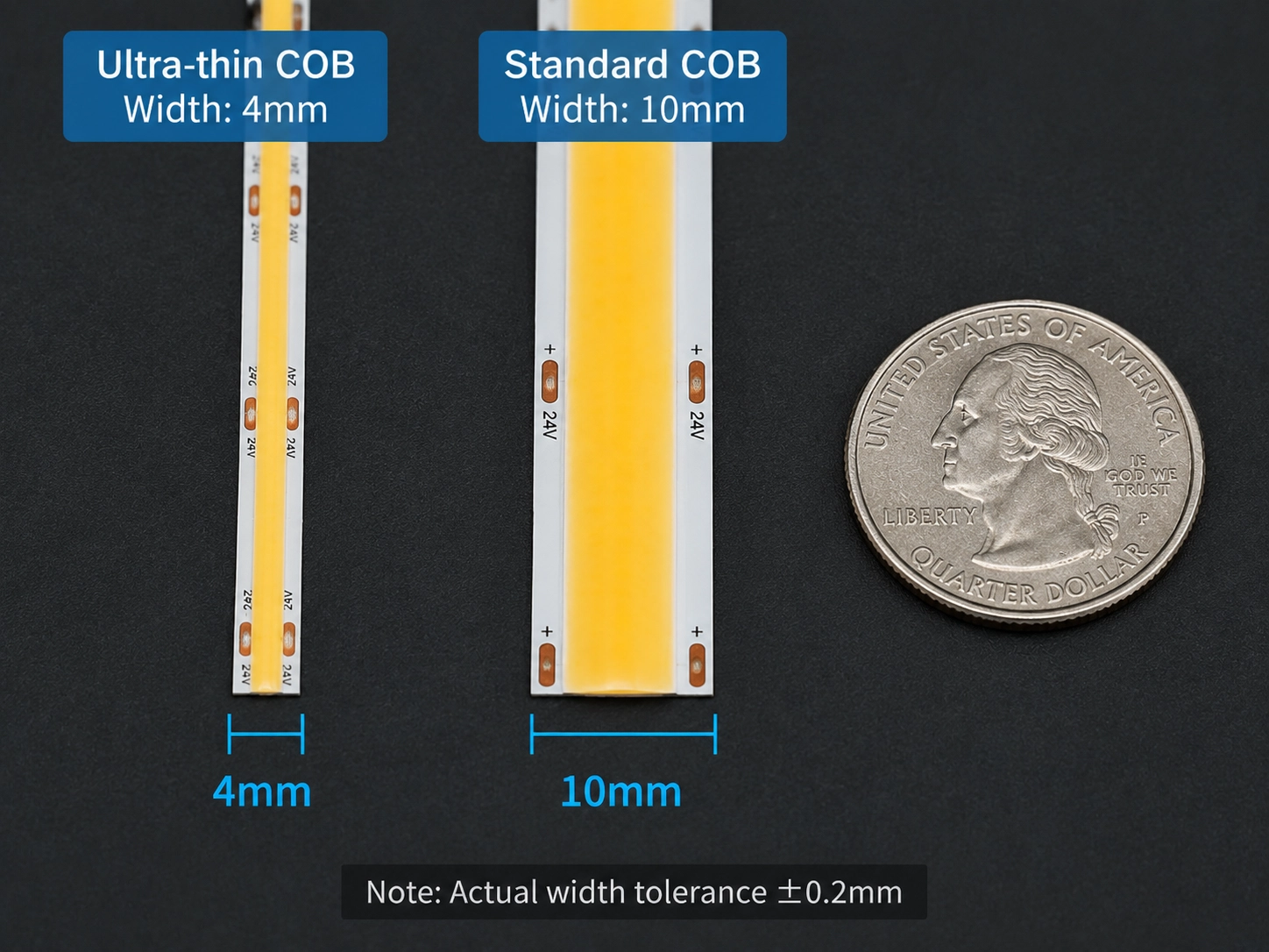
Główną różnicą między ultracienkimi taśmami LED COB a standardowymi taśmami LED COB jest równowaga między elastycznością instalacji a wydajnością inżynierską. Ultracienkie paski COB o szerokościach PCB o szerokości 2,7 mm–5 mm są przeznaczone do zastosowań o ograniczonej przestrzeni, podczas gdy standardowe paski COB o szerokości 8 mm–10 mm zapewniają większą pojemność elektryczną, margines termiczny i ogólną niezawodność.
Wybór między nimi zależy od tego, czy projekt traktuje priorytetowo minimalny ślad instalacji, czy maksymalną tolerancję wydajności.
1. Różnice konstrukcyjne i inżynieryjne
Ultracienkie paski LED COB zapewniają mniejszy ślad instalacyjny, zmniejszając szerokość płytki drukowanej i optymalizując układ komponentów. Pozwala to na dopasowanie się do wąskich kanałów, konstrukcji mebli i ukrytych aplikacji oświetleniowych, w których standardowe paski LED mogą nie być odpowiednie.
Ta szczelina w obszarze miedzi (patrz ograniczenia szerokości płytki drukowanej powyżej) jest powodem, dla którego standardowe paski COB (8–10 mm) tolerują wyższą gęstość mocy bez dodatkowych akcesoriów termicznych, podczas gdy ultracienkie konstrukcje (2,7–5 mm) zazwyczaj wymagają profili aluminiowych, aby osiągnąć tę samą niezawodność. Dla projektantów przekłada się to na bezpośredni kompromis: każdy milimetr szerokości płytki drukowanej za ukrycie przenosi więcej obciążenia termicznego i elektrycznego z miedzi PCB na system instalacyjny (profil, rozmiar sterownika, punkty wtrysku).
| Czynnik inżynierski | Ultracienki COB (2,7 mm–5 mm) | Standardowy COB (8mm-10mm) |
| Główna przewaga | Minimalny ślad instalacji i maksymalne ukrycie | Wyższy margines wydajności i zwiększona niezawodność |
| Pojemność miedzi PCB | Niższy obszar miedzi; wymaga starannego planowania zasilania | Wyższa pojemność miedzi do lepszej obsługi prądu |
| Rozpraszanie ciepła | Bardziej zależne od profili aluminiowych i warunków montażowych | Lepsza naturalna pojemność cieplna dzięki szerszej strukturze PCB |
| Elastyczność instalacji | Doskonały do wąskich przestrzeni, ukrytych kanałów i precyzyjnych projektów | Lepsze dla ogólnych aplikacji wymagających łatwiejszej integracji |
| Najlepsze aplikacje | Meble, ekspozycje, szafki, ukryte oświetlenie architektoniczne | Oświetlenie wielkopowierzchniowe, projekty komercyjne, ogólne zastosowania architektoniczne |
Zasada wyboru
Wybór między ultracienkim i standardowym COB sprowadza się do tego samego kompromisu, o którym mowa w Jak wybrać odpowiednią szerokość płytki drukowanej: ślad instalacji w porównaniu z marginesem elektrycznym i termicznym. Ultracienkie paski COB wygrywają w przestrzeni i ukrywaniu; standardowe paski COB wygrywają pod względem pojemności i niezawodności — właściwy wybór zależy od tego, które ograniczenie ma większe znaczenie dla konkretnego projektu.
Jak zainstalować ultra cienkie światła taśmowe LED COB?
Prawidłowe zainstalowanie ultracienkich listew LED COB wymaga zaplanowania profilu aluminiowego i wtrysku zasilania przed instalacją, ostrożne obchodzenie się z wąską płytką drukowaną podczas cięcia i montażu, testowanie całego systemu przed końcowym montażem i diagnozowanie awarii przez objaw (ściemnianie vs przegrzanie) zamiast zgadywania.
1. Przed instalacją: planowanie przestrzeni, profilu i zasilania
Przed instalacją należy zweryfikować rzeczywiste wymiary taśmy LED i otoczenia montażu. Ultracienkie paski LED COB dostępne są w wąskich formatach, takich jak 2,7 mm, 3 mm, 4 mm i 5 mm, ale kanał instalacyjny nie powinien być zaprojektowany tylko zgodnie z szerokością PCB. Właściwa przestrzeń instalacyjna powinna uwzględniać tolerancję szerokości PCB, wymiary profilu wewnętrznego, przestrzeń do prowadzenia kabli, grubość dyfuzora i dostępność konserwacji.
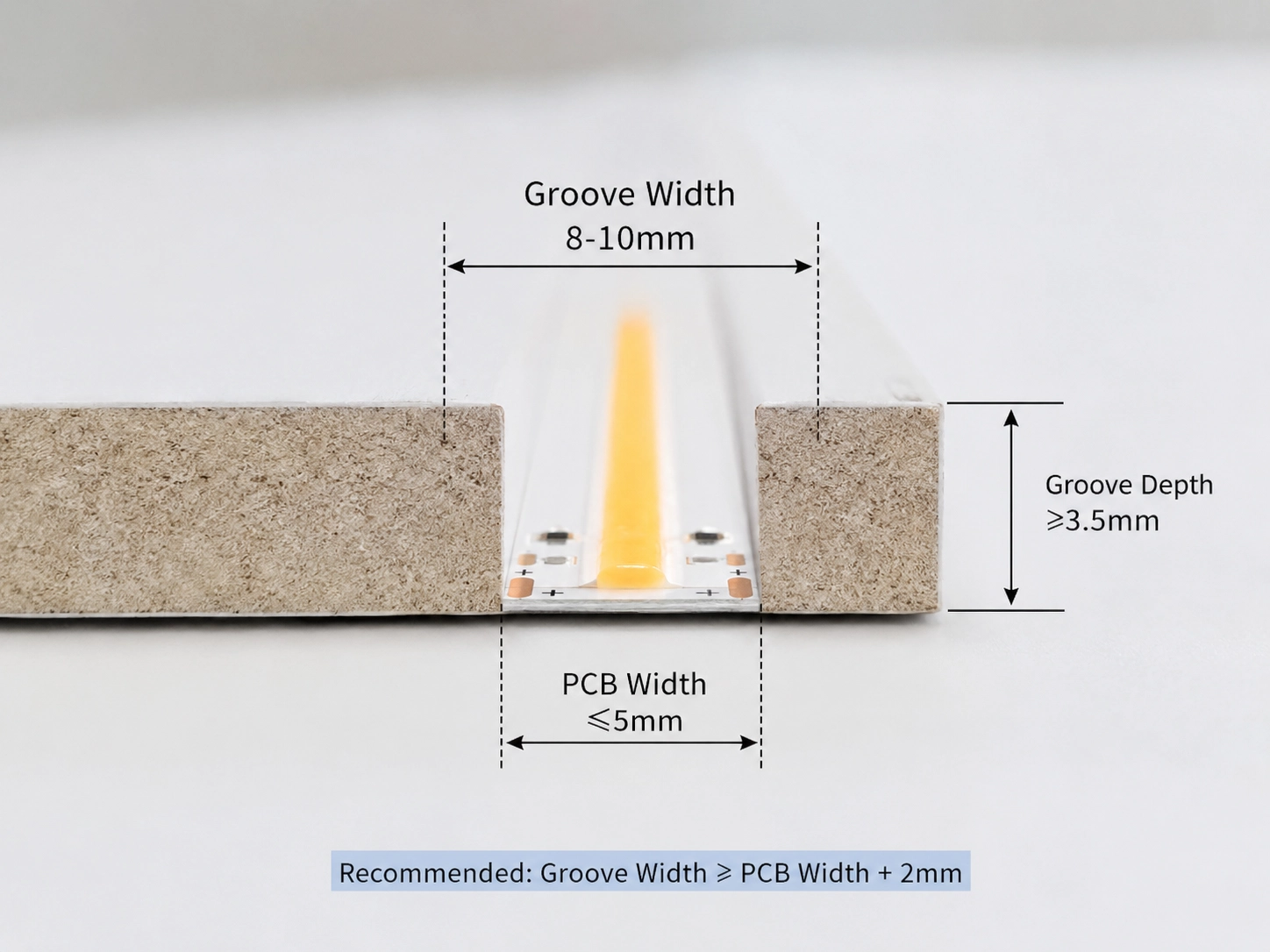
Wybór profilu aluminiowego powinien być oparty zarówno na dopasowaniu, jak i gęstości mocy, a nie dopasowaniu sam. Ponieważ węższe płytki drukowane mają mniej miedzi do rozprowadzania ciepła (patrz ograniczenia szerokości płytki drukowanej powyżej), profil staje się podstawową ścieżką ciepła — wybierz jedną z wartością rzeczywistej paska w/m, a nie tylko taką, która pasuje do szerokości płytki drukowanej. Zbyt wąski profil powoduje naprężenie mechaniczne i ogranicza wymianę ciepła; zbyt duży zmniejsza wydajność optyczną i wpływa na wygląd końcowy. Ten przewodnik na Jak używać profili aluminiowych do oświetlenia pośredniego Obejmuje wybór profilu dla ukrytych aplikacji bardziej szczegółowo.
Planowanie zasilania powinno również nastąpić na tym etapie. Spadek napięcia wynika bezpośrednio z ograniczonej pojemności miedzi PCB (patrz ograniczenia elektryczne); zadanie planowania polega na obliczeniu odstępu punktów wtrysku przed rozpoczęciem okablowania. Zasadniczo dodawaj punkt wtrysku mocy co 5 metrów dla ultracienkiego COB 24 V, który działa powyżej 10 W/m i skrócić ten interwał dla systemów 12 V lub projektów o większej mocy. Ten przewodnik na Kiedy wybrać systemy taśmowe LED 12V, 24V lub 48V Wyjaśnia, jak wybór napięcia wpływa na prąd i długość instalacji.
2. Podczas instalacji: cięcie, podłączenie i obsługa
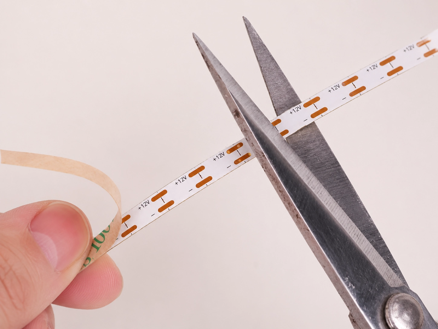
Ultracienkie paski COB należy wycinać tylko w wyznaczonych punktach cięcia, aby zapobiec uszkodzeniu obwodów wewnętrznych i segmentów LED. Ponieważ wąskie płytki drukowane zawierają mniejsze miedziane podkładki, praca przyłączeniowa wymaga większej precyzji niż standardowe paski LED — dla niestandardowych długości lutowanie często zapewnia bardziej niezawodny kontakt niż złącza uniwersalne, które mogą nie zapewniać wystarczającego nacisku styku na ultrawęższych płytkach drukowanych.
Paski pozostają elastyczne, ale ich zmniejszona szerokość sprawia, że są bardziej wrażliwe na stres fizyczny. Postępuj zgodnie z określonym minimalnym promieniem gięcia, unikaj ostrych zagięć lub powtarzającego się zginania w tym samym punkcie i chroń obszary połączeń przed naprężeniem mechanicznym — jest to szczególnie ważne w przypadku pasków 2,7 mm i 3 mm, które mają mniej zbrojenia mechanicznego niż szersze konstrukcje.
Podkład klejowy powinien być nakładany tylko na czyste, suche, stabilne powierzchnie; kurz, olej lub wilgoć zmniejsza przyczepność i może powodować ruch w czasie. W przypadku wymagających środowisk dodaj zaciski mechaniczne, mocowanie profilu aluminiowego lub niestandardowe konstrukcje montażowe, zamiast polegać na samym kleju.
3. Po instalacji: testowanie i weryfikacja
Profil aluminiowy powinien być zainstalowany i dopasować przed końcowym montażem, aby potwierdzić, że listwa pasuje prawidłowo, prowadzenie kabli jest praktyczne, a wydajność termiczna spełnia wymagania. Ten przewodnik na Jak zainstalować aluminium LED profilu Obejmuje ogólne techniki montażu mające zastosowanie do profili wąskokanałowych.
Zanim konstrukcja oświetlenia zostanie trwale uszczelniona, przetestuj cały system pod kątem spójności jasności, jednorodności kolorów, migotania, akumulacji ciepła i stabilności połączenia. Identyfikacja problemów na tym etapie — a nie po zamknięciu konstrukcji — pozwala uniknąć kosztownych przeróbek.

4. Typowe awarie i jak je zdiagnozować
Opisane powyżej ograniczenia elektryczne i termiczne pojawiają się podczas pracy jako dwa rozpoznawalne objawy: ściemnianie na końcu paska i zlokalizowane przegrzanie. Diagnozowanie, który widzisz, wskazuje bezpośrednio na poprawkę:
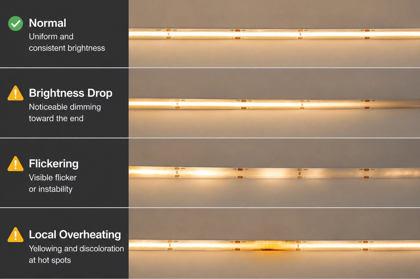
| Objaw awarii | Możliwa przyczyna inżynierska | Zalecane rozwiązanie |
| Jasność zmniejsza się wzdłuż paska | Spadek napięcia spowodowany długimi biegami lub niewystarczający rozkład mocy | Optymalizuj wybór napięcia, skracaj ciągi ciągłe i dodaj punkty wtrysku mocy |
| Nadmierne ciepło podczas pracy | Niewystarczająca ścieżka termiczna lub zła konstrukcja odprowadzania ciepła | Użyj odpowiedniego profilu aluminiowego, aby poprawić transfer ciepła |
| Migotanie lub niestabilne oświetlenie | Niestabilne zasilanie, słabe okablowanie lub niewiarygodne złącza | Sprawdź pojemność sterownika, jakość okablowania i punkty podłączenia |
| Nierównomierne oświetlenie | Nieprawidłowy wybór dyfuzora lub złe dopasowanie profilu | Dostosuj projekt optyczny i wybierz kompatybilne profile |
| Uszkodzenie mechaniczne lub przerwanie światła | Nadmierne zginanie, skręcanie lub naprężenie instalacyjne | Postępuj zgodnie z podanym promieniem gięcia i ostrożnie obchodź się z płytką drukowaną |
Większość przypadków ściemniania sięga do brakującego punktu wtrysku zasilania, a nie do defektu paska; ten przewodnik na Jak zapobiegać spadkom napięcia w długich instalacjach świetlnych taśmy LED Obejmuje bardziej szczegółowo odstępy wtryskowe. Przypadki przegrzania zwykle wskazują na niewymiarowy lub nieobecny profil aluminiowy w stosunku do gęstości mocy paska.
Najlepszym podejściem jest zidentyfikowanie tych ograniczeń inżynieryjnych na etapie projektowania — szerokość płytki drukowanej, planowanie zasilania i wybór profilu — zamiast korygowania problemów z wydajnością po zainstalowaniu i uszczelnieniu konstrukcji oświetlenia.
FAQ
Wniosek
ultracienki Taśmy LED COB nie są definiowane tylko przez ich wąski rozmiar. Ich prawdziwa wartość inżynierska wynika z rozwiązywania wyzwań związanych z integracją oświetlenia, w których przestrzeń instalacyjna, wygląd i wymagania dotyczące wydajności muszą być zrównoważone.
Kluczową zasadą ultracienkiego projektu COB jest to, że zmniejszenie szerokości PCB zawsze wiąże się z kompromisami inżynieryjnymi. Węższy pasek zapewnia lepsze ukrycie i większą elastyczność instalacji, ale także zmniejsza pojemność miedzi, marginesy termiczne i tolerancję mechaniczną.
Udane ultracienkie projekty oświetlenia LED wymagają kompletnego podejścia systemowego:
- Wybierz szerokość PCB na podstawie rzeczywistych ograniczeń instalacji.
- Rozważ napięcie, pojemność prądu i długość pracy podczas projektowania elektrycznego.
- Do zarządzania termicznego należy stosować odpowiednie profile aluminiowe.
- Dopasuj metody instalacji z warunkami mechanicznymi i środowiskowymi.
- Oceń wymagania optyczne, takie jak jednorodność, odległość widzenia i kontrola olśnienia.
Najlepsze ultracienkie rozwiązanie COB LED nie jest najmniejszą dostępną konstrukcją, ale takie, które zapewnia prawidłową równowagę między kompaktową integracją, niezawodną wydajnością i długoterminową stabilnością.
Rozumiejąc związek między strukturą PCB, technologią COB, zachowaniem termicznym i wymaganiami instalacyjnymi, inżynierowie mogą skuteczniej wybierać i integrować ultracienkie systemy LED do zastosowań meblowych, detalicznych, architektonicznych, motoryzacyjnych i precyzyjnych.
Powiązane posty