Türkçe
  English
  简体中文
简体中文  Deutsch
  Español
  Français
  Italiano
  日本語
日本語  한국어
한국어  Polski
  Português
  Русский
  Nederlands
  Tiếng Việt
  ไทย
ไทย 
Aydınlatma ürünleri küçülmeye devam ettikçe, kurulum alanı en büyük tasarım kısıtlamalarından biri haline geldi. Ultra ince LED şerit ışıkları, COB teknolojisi ile sürekli, noktasız aydınlatmayı korurken PCB genişliğini azaltarak bu zorluğu çözer. Geleneksel LED şeritlerle karşılaştırıldığında, standart şeritlerin gizlenemeyeceği çok daha dar oluklara, alüminyum profillere, mobilya detaylarına, vitrinlere ve mimari özelliklere sığarlar.
Bununla birlikte, PCB genişliğini azaltmak, fiziksel boyutlardan çok daha fazlasını etkiler. Daha dar bir devre kartı, akım taşıma kapasitesini, ısı dağılımını, mekanik mukavemeti, voltaj düşüşü özelliklerini ve kurulum toleransını değiştirir. Bu nedenle en küçük şerit her zaman en iyi seçim değildir. Her proje, mevcut alanın, aydınlatma performansının, güvenilirliğin ve uzun vadeli çalışma koşullarının dengelenmesini gerektirir.
Bu makale ne kadar ince olduğunu açıklıyor COB LED şeritler Kompakt form faktörünü, hangi pratik genişlik seçeneklerinin mevcut olduğunu, her boyutun en uygun olduğu ve hangi tasarım faktörlerinin kurulum kalitesini ve servis ömrünü etkilediğini elde edin. İster mobilya, ister perakende ekranlar, mimari detaylar veya hassas uygulamalar için aydınlatma belirtiyor olun, aşağıdaki bölümler doğru şerit genişliğini seçmek ve yaygın tasarım hatalarından kaçınmak için pratik bir çerçeve sağlar.
Ultra ince LED şerit ışıklar nelerdir?
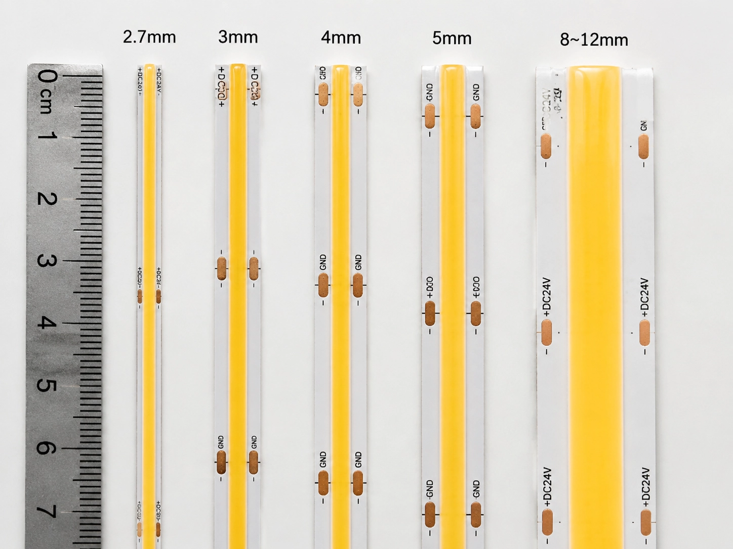
Ultra ince COB LED şerit ışıkları, tipik olarak 2,7 mm ila 5 mm genişliğinde, ultra dar PCB'ler ile tasarlanmış COB (board yonga üzerine) teknolojisine dayalı kompakt LED aydınlatma sistemleridir. Standart LED şeritlerin sığamayacağı, sürekli, noktasız aydınlatma sağlarken, alan kısıtlamalı kurulumlar için geliştirilmiştir.
Ultra ince LED şerit ışıklar, şeridin fiziksel kalınlığı değil, öncelikle PCB genişliği ile tanımlanır. Tipik olarak 8–12 mm PCB kullanan geleneksel LED şeritlerle karşılaştırıldığında, ultra ince COB tasarımları, devre kartı genişliğini dar kanallara, mobilya detaylarına, vitrinlere, gömme aydınlatmaya ve gizli kurulumun gerekli olduğu mimari uygulamalara uyacak şekilde azaltır.
COB (Chip-on-Board) teknolojisi, LED çiplerini ayrı LED paketler kullanmak yerine doğrudan PCB'ye monte ederek ultra ince tasarımlar sağlar. Bu kompakt yapı, optik ayak izini azaltır, LED yoğunluğunu artırır ve sürekli bir fosfor kaplamanın düzgün, noktasız aydınlatma ile kesintisiz ışık yayan bir yüzey oluşturmasına olanak tanır. Bununla birlikte, PCB genişliğinin azaltılması aynı zamanda mühendislik takasları da yaratır. Daha dar bir PCB, voltaj düşüşünü, termal performansı, maksimum kurulum uzunluğunu ve mekanik güvenilirliği etkileyebilen akım taşıma ve ısı dağılımı için daha az bakır alanı içerir. Bu nedenle, en iyi ultra ince LED şerit her zaman mevcut olan en dar seçenek değil, projenin aydınlatma gereksinimlerini, elektrik kapasitesini, termal koşullarını ve uzun vadeli güvenilirlik ihtiyaçlarını karşılayan en dar tasarımdır.
Ultra ince LED şerit genişliği kılavuzu
| PCB Genişliği | Kategori | En iyi uygulamalar | seçim nedeni |
| 2.7mm | Mikro koçanı şeridi | Otomotiv iç mekanları, hassas aydınlatma tesisatları | Son derece sınırlı alanlar için maksimum gizleme |
| 3mm | Ultra dar koçanı şeridi | Takı ekranları, minyatür dolaplar, birinci sınıf iç mekanlar | En küçük pratik profesyonel kurulum ayak izi |
| 4mm | Ultra ince koçanı şeridi | Mobilya, Dolap, Değirmencilik, Konut Projeleri | Kompakt boyut ve güvenilirlik arasında en iyi denge |
| 5 mm | İnce koçanı şeridi | Perakende ekranlar, mimari aydınlatma, daha uzun işletim uygulamaları | Daha iyi termal performans ve elektrik kararlılığı |
| 8–12 mm | Standart LED Şerit (SMD & COB) | Genel konut ve ticari aydınlatma | Daha yüksek performans marjı ve daha kolay entegrasyon |
Anahtar paket
Ultra ince LED şerit ışıklar, kurulum alanı, aydınlatma performansı ve uzun vadeli güvenilirlik arasındaki dengeye göre seçilir. Daha dar PCB'ler daha iyi gizleme ve daha fazla kurulum esnekliği sağlar, ancak aynı zamanda elektrik ve termal marjları da azaltır. Optimal seçim, istenen uygulama için kararlı aydınlatma, uygun ısı yönetimi ve güvenilir çalışmayı koruyabilen en dar PCB genişliğidir.
COB teknolojisi LED şeritleri nasıl ultra ince yapar?
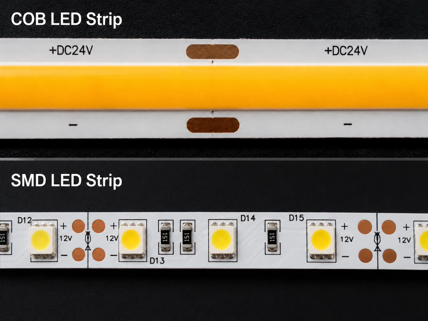
COB (Chip-on-board) teknolojisi, PCB'de LED çiplerin nasıl düzenlendiğini değiştirerek ultra ince LED şerit tasarımlarını mümkün kılar. CoB teknolojisi, bireysel SMD LED paketlerini kullanmak yerine, geleneksel LED ambalajların ihtiyaç duyduğu ekstra alanı ortadan kaldırarak çıplak LED çiplerini doğrudan devre kartına monte eder.
Bu kompakt çip düzenlemesi LED yoğunluğunu arttırır, optik ayak izini azaltır ve üreticilerin sürekli, noktasız aydınlatmayı korurken 2,7 mm ila 5 mm genişliğinde ultra dar PCB tasarımları geliştirmelerini sağlar.
Önemli Çıkarımlar
- Doğrudan çip montajı paket alanını azaltır: COB, LED çiplerini doğrudan PCB'ye yerleştirir ve geleneksel SMD şeritlerinde kullanılan daha büyük bireysel LED paketlerini ortadan kaldırır. COB şeritlerinin daha dar PCB genişliklerini elde etmesinin birincil nedeni budur.
- Daha yüksek talaş yoğunluğu sürekli aydınlatma yaratır: COB teknolojisi, çipleri birbirine daha yakın yerleştirerek, fosfor kaplamanın tek tek ışık kaynaklarını görünür LED noktaları olmadan tek tip bir yüzeye karıştırmasına olanak tanır.
- Azaltılmış optik ayak izi kurulum esnekliğini artırır: COB teknolojisi, LED şeritlerin dar kanallara, mobilya detaylarına, vitrinlere ve gizli aydınlatma yapılarına sığmasına izin vererek görünür ışık yayan alanı en aza indirir.
- Ultra ince tasarımlar ek mühendislik kontrolü gerektirir: PCB genişlikleri küçüldükçe, termal yayılma ve elektrik kapasitesi daha sınırlı hale gelir. Kompakt COB tasarımları, çip düzeninin, PCB yapısının, ısı dağılımının ve güç yönetiminin dikkatli bir şekilde optimizasyonunu gerektirir.
Her paketlenmiş LED'in ek montaj alanı kapladığı geleneksel SMD LED şeritlerinden farklı olarak, COB LED şeritleri çıplak LED çiplerini doğrudan devre kartına yerleştirir. Üreticiler, paket aralığını kaldırarak çip yoğunluğunu artırabilir ve genel PCB genişliğini azaltabilir.
Süreç, PCB'yi küçültmekten daha fazlasını içerir. Ultra dar COB LED şeridi elde etmek, yarı iletken ambalaj, PCB düzeni, talaş aralığı, optik tasarım, ısı dağılımı ve üretim hassasiyetinin koordineli optimizasyonunu gerektirir. Her faktör, kompakt boyutlar, ışık performansı, güvenilirlik ve uzun vadeli çalışma kararlılığı arasındaki dengeyi etkiler.
1. Doğrudan çip montajı
Doğrudan çip montajı, COB LED şeritlerinin geleneksel SMD şeritlerinden çok daha dar PCB genişliklerine ulaşabilmesinin başlıca nedenidir. Bireysel LED paketleri pano alanını işgal etmeden, üreticiler çipleri birbirine çok daha yakın konumlandırarak görünür parlaklık boşluklarını azaltırken sürekli bir ışık hattı oluşturabilir. Bu daha yüksek entegrasyon, şerit aydınlatılmış yüzeye yakın bir şekilde monte edildiğinde aydınlatma tutarlılığını da artırır.
2. Sürekli fosfor kaplama
Sürekli bir fosfor tabakası, yoğun bir şekilde düzenlenmiş LED çiplerini kaplar ve tek tek kalıplardan yayılan ışığı tek, tek tip bir ışıklı yüzeye karıştırır. Sonuç, görünür LED etkin noktalar olmadan pürüzsüz, noktasız aydınlatmadır. Bu optik özellik, ışık kaynağının genellikle yakın görüş mesafelerinde görülebildiği ve görsel tekdüzelik esas olan mobilya aydınlatması, mücevher ekranları, perakende rafları ve mimari ayrıntılar gibi uygulamalarda özellikle değerlidir.
3. Daha küçük optik ayak izi
Doğrudan çip montajını sürekli ışık emisyonu ile birleştiren COB teknolojisi, yüksek optik kaliteyi korurken görünür aydınlatma ayak izini azaltır. Bu, dar olukların içine kurulum sağlar, ince alümi̇nyum profi̇ller, gizli kanallar ve geleneksel LED şeritlerin aynı görsel etkiyi sağlayamadığı kompakt aydınlatma yapıları.
Ancak azaltılmış PCB genişliği, mühendislik takaslarını da sunar. Daha dar bir PCB, akım transferi ve ısı dağılımı için daha az bakır içerir, bu da voltaj düşüşü, termal performans ve maksimum çalışma uzunluğunu daha kritik tasarım hususları yapar. Bu nedenle, başarılı ultra ince COB LED şerit kurulumları sadece kompakt boyutlara değil, aynı zamanda uygun güç dağıtımına, termal yönetime ve kurulum yöntemlerine de bağlıdır.
| Mühendislik Faktörü | tarçınsız avantaj | tasarım etkisi |
| yonga yapısı | Doğrudan çip montajı | Daha dar PCB tasarımları sağlar |
| ışık çıkışı | Sürekli fosfor kaplama | Sorunsuz, noktasız aydınlatma yaratır |
| göz izi | Azaltılmış bileşen aralığı | Gizli ve kompakt kurulumlara uyar |
| PCB Genişliği | 2,7–5 mm düzenler | Dikkatli elektrik ve termal planlama gerektirir |
kilit nokta
COB teknolojisi, doğrudan çip montajı, sürekli fosfor kaplama ve kompakt bir optik yapıyı birleştirerek ultra ince LED şeritleri mümkün kılar. Bu yenilikler daha dar PCB genişliklerini ve daha iyi görsel entegrasyonu sağlarken, elektriksel ve termal marjları da azaltır. Başarılı tasarımlar bu nedenle, tek başına PCB genişliğini en aza indirmek yerine güç dağıtımı, ısı dağılımı ve uzun vadeli güvenilirlik ile kompakt boyut dengelemeye bağlıdır.

Ultra ince COB LED şeritlerinde PCB genişliği neden sınırlıdır?
PCB genişliği, ultra ince COB LED şeritlerinde sınırlıdır, çünkü PCB'yi azaltmak ayrıca bakır alanı, akım kapasitesini, ısı dağılımını ve mekanik mukavemeti de azaltır. Bu mühendislik kısıtlamaları, güvenilir performansı korurken bir COB LED şeridinin ne kadar dar olabileceğini belirler. Bu nedenle en iyi tasarım, elektrik, termal ve mekanik gereksinimleri karşılayan en dar PCB'dir.
Dar bir PCB neden voltaj düşüşünü artırır?
Dar bir PCB, elektrik akımını taşımak için daha az bakır içerdiğinden voltaj düşüşünü artırır. Elektrik direncindeki artış, akım taşıma kapasitesini azaltır ve güvenilir şerit uzunluğunu sınırlar. Ultra ince COB LED şeritlerinde, daha dar PCB'ler daha az iletken malzeme içerir, bu da elektrik direncini arttırır ve akım taşıma kapasitesini azaltır.
Bu, çeşitli mühendislik zorluklarına yol açabilir:
- Daha yüksek voltaj düşüşü: Daha uzun kurulumlar, şeridin sonuna doğru parlaklık azalması yaşayabilir.
- Daha düşük güç toleransı: Dar PCB'ler, yüksek akımlı işlem için daha az marja sahiptir.
- Daha kısa sürekli çalışma: Daha geniş LED şeritlere kıyasla maksimum kurulum uzunluğu genellikle azaltılır.
Bu nedenle, ultra ince COB LED şeritleri seçerken güç planlaması kritik öneme sahiptir. Kurulumdan önce çalışma voltajı, metre başına güç tüketimi, şerit uzunluğu ve sürücü kapasitesi gibi faktörler değerlendirilmelidir.
24V sistemler, aynı güç çıkışı için 12V'ye kıyasla akımı yarı yarıya azaltır, bu da voltaj düşüşünü azaltır ve ultra ince COB kurulumlarında daha uzun sürekli çalışmaları destekler. Ancak, gerçek performans hala PCB tasarımına, güç yoğunluğuna ve kurulum koşullarına bağlıdır. Referans için, bu kılavuz açıklar 24v COB LED şeridi güç enjeksiyonu olmadan ne kadar süre çalışabilir? ve maksimum çalışma uzunluğunu etkileyen faktörler.
Dar bir PCB neden ısıyı daha az verimli bir şekilde dağıtır?
Dar bir PCB, ısıyı LED çiplerinden uzaklaştırmak için daha az bakır alanına sahip olduğu için ısıyı daha az verimli bir şekilde dağıtır. Çalışma sıcaklığı arttıkça, etkin termal yönetim, LED performansını ve hizmet ömrünü korumak için giderek daha önemli hale gelir. PCB bakır tabakası sadece elektrik akımı taşımakla kalmaz, aynı zamanda LED çipleri tarafından üretilen ısının yayılmasına da yardımcı olur.
PCB genişliği azaldığında, mevcut bakır alanı küçülür ve doğal termal yolu azaltır. Bu, özellikle yüksek parlaklıkta uygulamalar veya uzun çalışma saatleri olan kurulumlar için harici ısı yönetimini giderek daha önemli hale getirir.
Ultra ince COB LED şeritler, şunları sağladığı için genellikle alüminyum profiller gerektirir:
- LED çiplerden uzakta ısı transferi geliştirildi
- Daha kararlı çalışma sıcaklığı
- Kapalı alanlarda aşırı ısınmaya karşı koruma
- Daha iyi uzun vadeli LED güvenilirliği
Yeterli termal yönetim olmadan aşırı ısı LED verimliliğini azaltabilir, malzeme yaşlanmasını hızlandırabilir ve aydınlatma sisteminin servis ömrünü kısaltabilir.
Ultra dar PCB'lerin üretilmesi neden daha zordur?
Ultra dar PCB'lerin üretimi daha zordur çünkü daha küçük bakır pedler ve daha dar yapılar mekanik mukavemeti azaltır ve üretim toleranslarını artırır. Daha dar bir PCB daha az fiziksel desteğe ve daha küçük bağlantı alanlarına sahiptir, bu da onu bükme stresine, konektör hizalamasına ve kurulum işlemeye daha duyarlı hale getirir.
Önemli hususlar şunları içerir:
- Minimum bükülme yarıçapı
- Konektör Uyumluluğu
- lehimleme kalitesi
- PCB esnekliği ve dayanıklılığı
- üretim tutarlılığı
Son derece dar PCB tasarımları, küçük değişiklikler elektrik performansını ve kurulum güvenilirliğini etkileyebileceğinden hassas üretim kontrolü gerektirir.
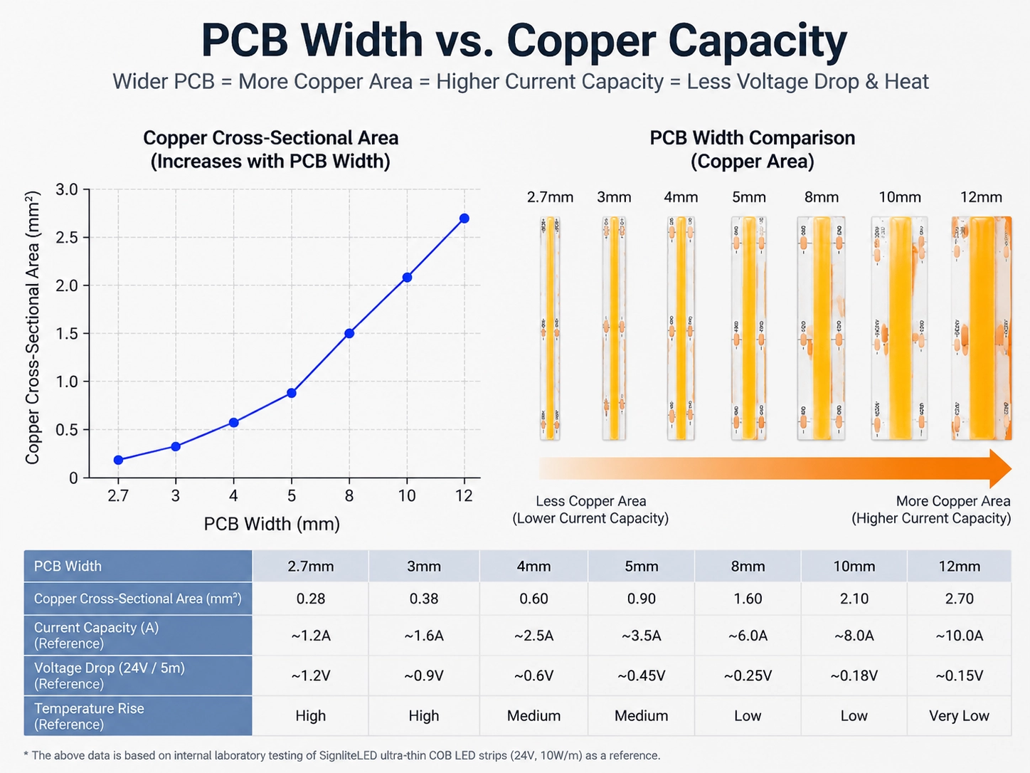
Anahtar tasarım prensibi
Minimum pratik PCB genişliği, boyut küçültmenin mühendislik gereksinimleriyle dengelenmesiyle belirlenir. Ultra ince COB LED şeritler mükemmel gizleme sağlar, ancak performansları uygun elektrik planlamasına, termal tasarıma ve kurulum yöntemlerine bağlıdır.
En küçük PCB'yi seçmek her zaman en iyi çözüm değildir. Optimal genişlik, istenen uygulama için yeterli elektrik kapasitesi, termal kararlılık ve mekanik güvenilirlik sağlayan genişliktir.
Doğru PCB genişliğini nasıl seçersiniz?
Ultra ince bir COB LED şeridi için doğru PCB genişliğini seçmek, kurulum alanı, elektrik performansı, termal yönetim ve uzun vadeli güvenilirlik dengeleme gerektirir. Mevcut en dar PCB her zaman en iyi seçim değildir. İdeal genişlik, yeterli performans marjlarını korurken projenin aydınlatma gereksinimlerini karşılayabilecek en küçük tasarımdır.
PCB genişliği, LED şeridin fiziksel boyutunu doğrudan etkiler, ancak aynı zamanda bakır kapasitesini, voltaj düşüşünü, ısı dağılımını ve mekanik gücü de etkiler. Bu nedenle profesyonel aydınlatma tasarımı, hem görünür kurulum gereksinimlerini hem de her PCB boyutunun arkasındaki mühendislik sınırlamalarını dikkate almalıdır.
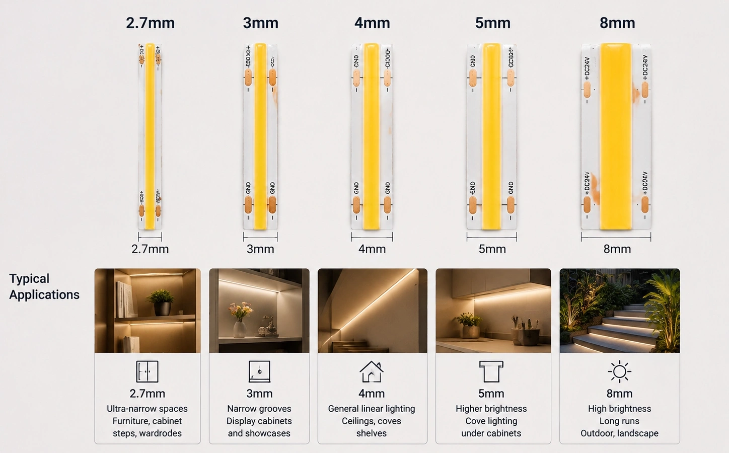
2.7mm COB LED Şerit: Maksimum minyatürleştirme
2,7 mm COB LED şerit, 3 mm'lik bir şeridin bile sığamayacağı otomotiv iç aydınlatması ve hassas ekran yapıları için kullanılan, piyasada bulunan en dar genişliktir.” Ana avantajı, biraz daha geniş LED şeritlerin bile kurulamadığı son derece sınırlı alanlara sığdırma yeteneğidir.
Tipik uygulamalar şunları içerir:
- Hassas ekran yapıları
- Otomotiv iç detayları
- Minyatür aydınlatma sistemleri
- Son derece gizli dekoratif tesisler
Son derece dar PCB, maksimum kurulum esnekliği sağlar, ancak aynı zamanda en düşük elektrik ve termal marjı da oluşturur. Daha az bakır alanı ile tasarımcılar akım kapasitesine, voltaj düşüşüne ve ısı dağılımına daha fazla dikkat etmelidir.
2,7 mm'lik bir COB LED şeridi, maksimum parlaklık veya uzun sürekli çalışma yerine alan sınırlamaları birincil endişe olduğunda en iyi şekilde seçilir.
3mm COB LED Şerit: Ultra dar profesyonel çözüm
3mm COB LED şerit, 2,7 mm'den daha iyi mekanik stabilite ile neredeyse görünmez gizlenme sunan, mücevher ekranları ve cam dolaplar için en yaygın olarak kullanılan ultra dar genişliktir. Güvenilir performansı korurken ışık kaynağının neredeyse görünmez kalması gereken uygulamalar için en popüler seçeneklerden biridir.
Yaygın uygulamalar şunları içerir:
- takı ekranları
- cam dolaplar
- Premium Mobilya Detay
- Küçük mimari aydınlatma özellikleri
2,7 mm tasarımlarla karşılaştırıldığında, 3 mm COB LED şeritler, son derece küçük bir kurulum ayak izini korurken, biraz geliştirilmiş elektrik ve mekanik stabilite sağlar.
Hassas aydınlatma projeleri için, gizleme ve görsel kalitenin maksimum güç kapasitesinden daha önemli olduğu durumlarda 3 mm genellikle tercih edilen bir seçimdir.

4mm COB LED Şerit: Boyut ve güvenilirlik arasındaki en iyi denge
4mm COB LED şerit, kabin ve mobilya aydınlatması için standart bir seçimdir, PCB bakır kapasitesini gizlenebilir bir ayak izi ile dengeler. Gizli kurulumlar için uygun kalırken, gelişmiş bakır kapasitesi, daha iyi termal performans ve daha güçlü mekanik güvenilirlik için yeterli PCB alanı sağlar.
Bu genişlik yaygın olarak kullanılır:
- Kabin aydınlatması
- Mobilya entegrasyonu
- İç dekorasyon
- Premium Konut Projeleri
Daha dar seçeneklerle karşılaştırıldığında, 4 mm tasarımlar voltaj düşüşüne, aşırı ısınmaya ve kurulum değişimine karşı daha fazla tolerans sağlar. Birçok profesyonel uygulama için bu genişlik, en iyi görünüm, performans ve güvenilirlik kombinasyonunu sunar.
5mm COB LED Şerit: Performans odaklı ince tasarım
5 mm COB LED şerit, perakende ekranlar ve daha uzun sürekli çalışma ve daha yüksek akım kullanımı gerektiren mimari aydınlatma için kullanılan en geniş ultra ince seçenektir.
Daha geniş PCB yapısı şunları sağlar:
- Daha iyi akım kullanımı
- İyileştirilmiş ısı dağılımı
- Daha güvenilir uzun vadeli işlem
- Daha kolay kurulum uyumluluğu
5 mm COB LED şeritler, perakende ekranlar, ticari aydınlatma, mimari uygulamalar ve daha uzun çalışma saatleri gerektiren projeler için yaygın olarak seçilir.
Biraz daha fazla kurulum alanı gerektirmelerine rağmen, artan mühendislik marjları, onları güvenilirliğin mümkün olan en küçük ayak izini elde etmekten daha önemli olduğu ortamlar için uygun hale getirir.
Ultra ince COB LED şeritler için PCB genişlik seçim kılavuzu
| PCB Genişliği | Tasarım Kategorisi | AVANTAJ | Tipik Uygulamalar | Mühendislik düşüncesi |
| 2.7mm | aşırı minyatürleştirme | Sınırlı alanlarda maksimum gizlenme | Hassas ekranlar, kompakt aydınlatma | En düşük termal ve elektrik marjı; dikkatli sistem tasarımı gerektirir |
| 3mm | Ultra dar koçanı tasarımı | En küçük pratik profesyonel kurulum ayak izi | Mücevher ekranları, mobilya detayları, birinci sınıf iç mekanlar | Güç dağıtımına ve ısı yönetimine dikkat edilmesini gerektirir |
| 4mm | Dengeli ultra ince tasarım | Boyut ve güvenilirlik arasında en iyi denge | Dolaplar, mobilyalar, mimari detaylar | En gizli aydınlatma projeleri için uygun |
| 5 mm | Performans odaklı ince tasarım | Geliştirilmiş termal ve elektriksel kararlılık | Perakende, ticari, uzun süreli aydınlatma | Güvenilirlik bir öncelik olduğunda daha iyi seçim |
| 8mm–10mm | Standart COB LED Şerit (COB'a özel ürün yelpazesi) | Daha yüksek performans marjı ve daha kolay entegrasyon | Geniş alanlı aydınlatma, genel uygulamalar | Daha fazla kurulum alanı gerektirir ancak daha güçlü kapasite sağlar |
seçim prensibi
Doğru PCB genişliği, kurulum kısıtlamaları ve sistem gereksinimleri arasındaki ilişkiye bağlıdır. Maksimum gizleme öncelik olduğunda 2,7 mm–3 mm COB LED şeritleri, görünüm ve güvenilirliği dengelerken 4 mm tasarımları ve geliştirilmiş termal performans ve daha uzun çalışma gerektiğinde 5 mm versiyonları seçin.
Ultra ince COB LED şerit tasarımının amacı, sadece PCB boyutunu küçültmek değil, aynı zamanda kompakt kurulum, kararlı aydınlatma ve uzun vadeli güvenilirliğin en iyi kombinasyonunu elde etmektir.
Ultra ince COB LED şeritler nerede kullanılır?
Ultra ince COB LED şeritler, temel olarak kurulum alanının sınırlı olduğu ancak sürekli, noktasız aydınlatmanın gerekli olduğu uygulamalarda kullanılır. Dar PCB yapıları, standart LED şeritlerin sığamayacağı gizli aydınlatma, hassas ekranlar, mobilya entegrasyonu ve mimari detaylar için idealdir.
Ultra ince COB LED şeritlerinin ana avantajı, sadece daha küçük boyutları değil, sınırlı alanlarda profesyonel aydınlatma performansı sağlama yetenekleridir. COB teknolojisini ultra dar PCB tasarımlarıyla birleştiren bu LED şeritler, temiz bir görsel görünüm sağlarken sorunsuz aydınlatma sağlar.
Mobilya ve dolap aydınlatması
Mobilya aydınlatması, ultra ince COB LED şeritler için en yaygın uygulamalardan biridir. Dolaplar, raflar, dolaplar ve yerleşik mobilyalar genellikle sınırlı kurulum derinliğine sahiptir ve bu da geleneksel LED şeritlerin görünür boşluklar veya büyük boy profiller olmadan entegre edilmesini zorlaştırır.
Kompakt boyutlar, parlaklık tutarlılığı ve termal güvenilirlik arasında iyi bir denge sağladıkları için bu uygulamalar için 4 mm ve 5 mm COB LED şeritler sıklıkla seçilir.
Tipik kullanımlar şunları içerir:
- mutfak dolabı alt aydınlatma
- gardırop iç aydınlatma
- kitap rafları ve vitrinler
- Özel mobilya vurgu aydınlatması
Dar PCB, tasarımcıların temiz, üstün bir görünüm sağlarken gizli ışık kaynakları oluşturmasına olanak tanır.
Mücevher ekranları ve hassas perakende aydınlatma
Ultra ince COB LED şeritler, özellikle görsel hassasiyetin kritik olduğu mücevher ekranları, cam dolaplar ve lüks perakende ortamları için uygundur.
3mm COB LED şeritler bu uygulamalarda sıklıkla tercih edilir, çünkü son derece dar form faktörü, ürünlerden dikkati dağıtmadan küçük ekran yapılarına kurulum sağlar.
Temel avantajlar şunları içerir:
- Sürekli noktasız aydınlatma
- Minimum görünür donanım
- Geliştirilmiş ürün vurgulama
- Kompakt ekran alanlarında esnek kurulum
Üst düzey perakende ortamları için, aydınlatma sistemi görünür bir tasarım öğesi olmaktan ziyade ürünü geliştirmelidir. Ultra ince COB LED şeritler bu gizli aydınlatma efektini elde etmenize yardımcı olur.
3. Mimari ve gizli aydınlatma uygulamaları

Mimari aydınlatma, tutarlı aydınlatmayı korurken genellikle LED kaynaklarının yapıda kaybolmasını gerektirir. Ultra ince COB LED şeritler yaygın olarak kullanılır:
- duvar teneke aydınlatma
- merdiven aydınlatması
- koy aydınlatma
- Doğrusal Mimari Detaylar
- Dekoratif dolaylı aydınlatma
Bu uygulamalarda, daha uzun çalışma süreleri için ek termal ve elektrik marjı sağladıkları için 4 mm ve 5 mm COB LED şeritler yaygın olarak seçilir.
Alüminyum profillerle doğru kurulum, mimari uygulamalar için özellikle önemlidir, çünkü bu sistemler genellikle sürekli çalışır ve zaman içinde istikrarlı bir parlaklık gerektirir.
Uygulama Seçimi Prensibi
Her genişliği doğru uygulamayla eşleştirmek, bu kılavuzda kullanılan aynı seçim ilkesini takip eder - tam karşılaştırma tablosu ve karar kriterleri için doğru PCB genişliğini nasıl seçtiğinize bakın.
Ultra ince COB LED şeritler, her standart LED şerit uygulamasını değiştirmek için tasarlanmamıştır. Mühendislik değerleri, kompakt boyut, sürekli aydınlatma ve profesyonel görünümün birincil gereksinimler olduğu kurulum zorluklarını çözmede yatmaktadır.
Ultra ince COB ve standart COB LED şeritler
Ultra ince COB LED şeritler ile standart COB LED şeritler arasındaki temel fark, kurulum esnekliği ile mühendislik performansı arasındaki dengedir. 2,7 mm–5 mm PCB genişliklerine sahip ultra ince COB şeritleri, alan kısıtlı uygulamalar için tasarlanmıştır, 8 mm–10 mm genişliklere sahip standart COB şeritleri daha fazla elektrik kapasitesi, termal marj ve genel güvenilirlik sağlar.
Aralarında seçim yapmak, projenin minimum kurulum ayak izine veya maksimum performans toleransına öncelik vermesine bağlıdır.
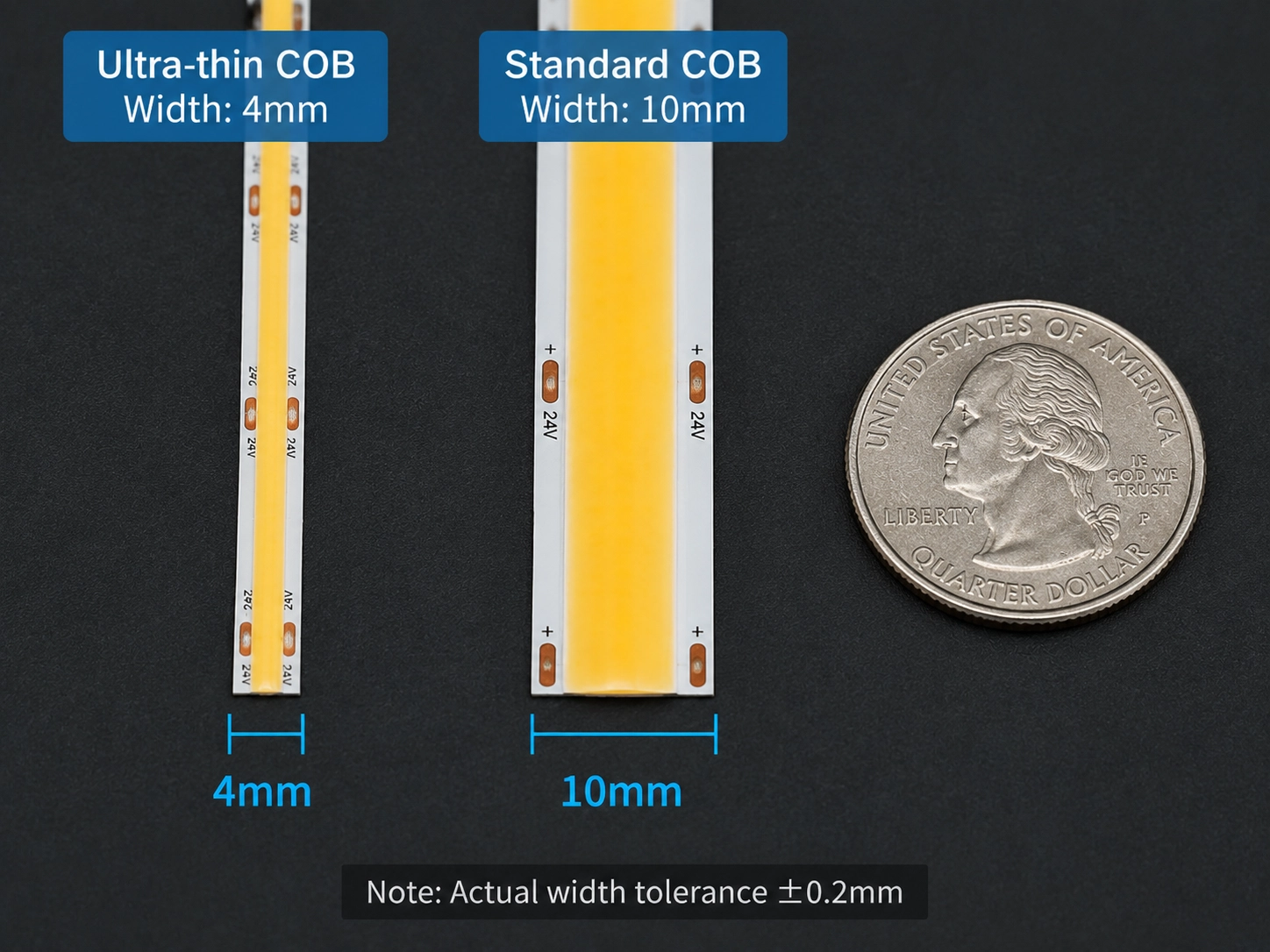
1. Yapısal ve Mühendislik Farklılıkları
Ultra ince COB LED şeritleri, PCB genişliğini azaltarak ve bileşen düzenini optimize ederek daha küçük bir kurulum ayak izi elde eder. Bu, standart LED şeritlerin uygun olmayabileceği dar kanallara, mobilya yapılarına ve gizli aydınlatma uygulamalarına sığmalarını sağlar.
Bu bakır alanı boşluğu (yukarıdaki PCB genişliği sınırlamalarına bakın), standart COB şeritlerinin (8–10 mm) ek termal aksesuarlar olmadan daha yüksek güç yoğunluğunu tolere etmesi, ultra ince tasarımların (2,7–5 mm) tipik olarak aynı güvenilirliğe ulaşmak için alüminyum profilleri gerektirmesinin nedenidir. Tasarımcılar için bu, doğrudan bir değiş tokuş anlamına gelir: gizlenme için takas edilen her milimetre PCB bakırından daha fazla termal ve elektrik yükünü kurulum sistemine (profil, sürücü boyutlandırma, enjeksiyon noktaları) kaydırır.
| Mühendislik Faktörü | Ultra ince COB (2.7mm–5mm) | Standart COB (8mm–10mm) |
| AVANTAJ | Minimum kurulum ayak izi ve maksimum gizleme | Daha yüksek performans marjı ve gelişmiş güvenilirlik |
| PCB bakır kapasitesi | daha düşük bakır alanı; dikkatli güç planlaması gerektirir | Gelişmiş akım taşıma için daha yüksek bakır kapasitesi |
| Isı Dağılımı | Alüminyum profillere ve kurulum koşullarına daha fazla bağlıdır | Daha geniş PCB yapısı sayesinde daha iyi doğal termal kapasite |
| Kurulum Esnekliği | Dar alanlar, gizli kanallar ve hassas tasarımlar için mükemmel | Daha kolay entegrasyon gerektiren genel uygulamalar için daha iyi |
| En iyi uygulamalar | Mobilya, vitrin, dolaplar, gizli mimari aydınlatma | Geniş alan aydınlatması, ticari projeler, genel mimari uygulamalar |
seçim prensibi
Ultra ince ve standart COB arasında seçim yapmak, doğru PCB genişliğini nasıl seçersiniz bölümündeki aynı değiş tokuşa iner: elektrik ve termal marj ile kurulum ayak izi. Ultra ince COB şeritleri, uzay ve gizlemede kazanır; standart COB şeritleri kapasite ve güvenilirlik ile kazanır - doğru seçim, belirli proje için hangi kısıtlamanın daha önemli olduğuna bağlıdır.
Ultra ince COB LED şerit ışıkları nasıl kurulur?
Ultra ince COB LED şeritlerinin doğru şekilde takılması, kurulumdan önce alüminyum profili ve güç enjeksiyonunu planlamayı, kesme ve montaj sırasında dar PCB'yi dikkatli bir şekilde ele almayı, son montajdan önce tüm sistemin test edilmesini ve tahmin yerine semptomlara göre arızaları (aşırı kararmaya karşı aşırı ısınma) teşhis etmeyi gerektirir.
1. Kurulumdan önce: alan, profil ve güç planlaması
Kurulumdan önce, LED şeridin ve montaj ortamının gerçek boyutları doğrulanmalıdır. Ultra ince COB LED şeritler 2,7 mm, 3 mm, 4 mm ve 5 mm gibi dar formatlarda mevcuttur, ancak kurulum kanalı sadece PCB genişliğine göre tasarlanmamalıdır. PCB genişliği toleransı, dahili profil boyutları, kablo yönlendirme alanı, difüzör kalınlığı ve bakım erişilebilirliği için uygun bir kurulum alanı hesaba katılmalıdır.
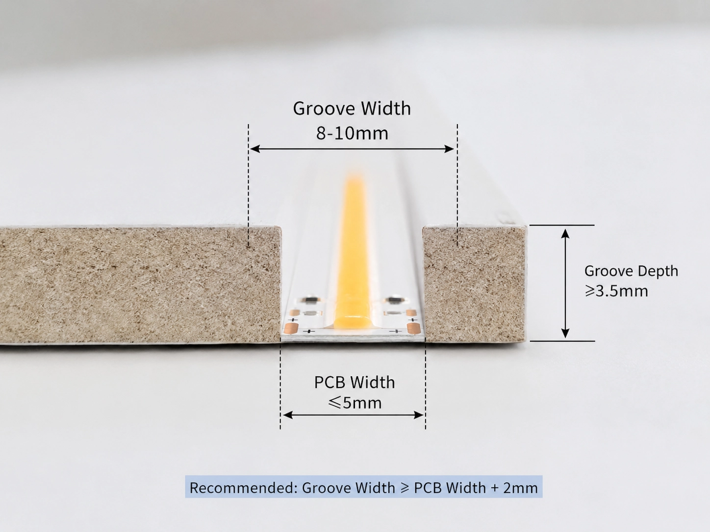
Alüminyum profil seçimi, tek başına uygun değil, hem uyum hem de güç yoğunluğuna dayanmalıdır. Daha dar PCB'ler ısı yayılması için daha az bakıra sahip olduğundan (yukarıdaki PCB genişliği sınırlamalarına bakın), profil birincil ısı yolu haline gelir - yalnızca PCB genişliğine uyan değil, şeridin gerçek w/m'si için derecelendirilen bir tane seçin. Çok dar olan bir profil mekanik stres yaratır ve ısı transferini kısıtlar; çok büyük olan optik verimliliği azaltır ve son görünümü etkiler. bu kılavuz Dolaylı aydınlatma için alüminyum profiller nasıl kullanılır? Gizli uygulamalar için profil seçimini daha ayrıntılı olarak kapsar.
Güç planlaması da bu aşamada yapılmalıdır. Voltaj düşüşü doğrudan PCB'nin sınırlı bakır kapasitesinden gelir (yukarıdaki elektriksel sınırlamalara bakın); Genel bir kural olarak, 24V ultra ince COB 10W/m'nin üzerindeki koşular için her 5 metrede bir güç enjeksiyon noktası ekleyin ve bu aralığı 12V sistemler veya daha yüksek güç tasarımları için kısaltın. bu kılavuz 12V, 24V veya 48V LED Şerit Sistemleri Ne Zaman Seçilir? Voltaj seçiminin akım ve kurulum uzunluğunu nasıl etkilediğini açıklar.
2. Kurulum sırasında: kesme, bağlantı ve taşıma
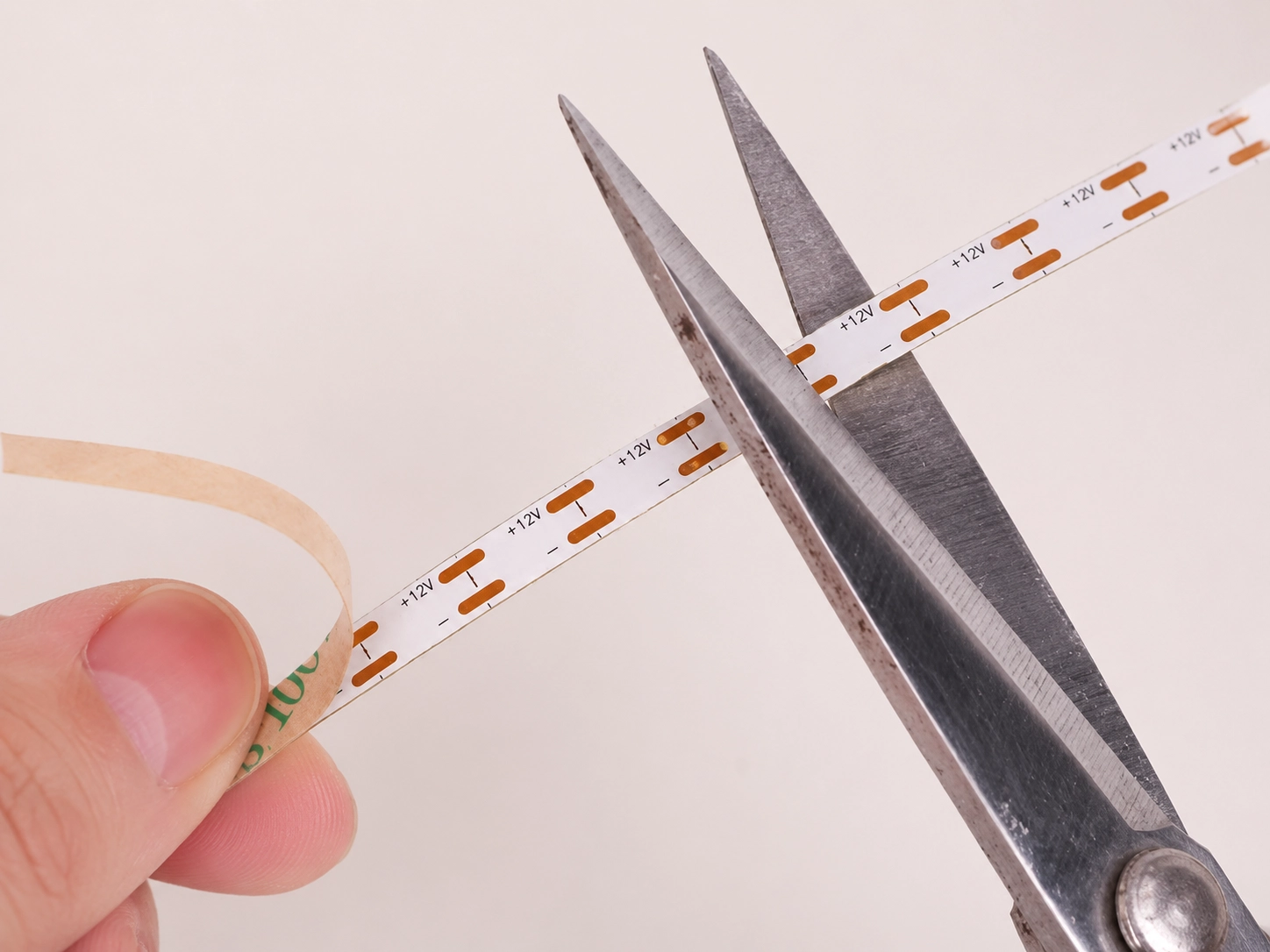
Ultra ince COB şeritleri, dahili devrelerin ve LED segmentlerinin zarar görmesini önlemek için yalnızca belirlenen kesme noktalarında kesilmelidir. Dar PCB'ler daha küçük bakır pedler içerdiğinden, bağlantı çalışması standart LED şeritlerden daha fazla hassasiyet gerektirir - özel uzunluklar için, lehimleme genellikle ultra dar PCB'ler üzerinde yeterli temas basıncı sağlamayan evrensel konektörlerden daha güvenilir temas sağlar.
Şeritler esnek kalır, ancak azaltılmış genişlikleri onları fiziksel strese karşı daha duyarlı hale getirir. Belirtilen minimum bükme yarıçapını takip edin, aynı noktada keskin kıvrımlardan veya tekrarlanan bükülmeden kaçının ve bağlantı alanlarını mekanik stresten koruyun - bu, özellikle daha geniş tasarımlardan daha az mekanik takviyeye sahip 2,7 mm ve 3 mm şeritler için önemlidir.
Yapıştırıcı destek sadece temiz, kuru, kararlı yüzeylere uygulanmalıdır; toz, yağ veya nem yapışmayı azaltır ve zaman içinde hareket etmeye neden olabilir. Zorlu ortamlar için, yalnızca yapıştırıcıya güvenmek yerine mekanik klipsler, alüminyum profil montajı veya özelleştirilmiş montaj yapıları ekleyin.
3. Kurulumdan sonra: test ve doğrulama
Şeridin doğru oturduğunu, kablo yönlendirmesinin pratik olduğunu ve termal performansın gereksinimleri karşıladığını doğrulamak için alüminyum profilin son montajdan önce monte edilmesi ve test edilmesi gerekir. bu kılavuz LED profil alüminyum nasıl kurulur Dar kanallı profillere uygulanabilen genel montaj tekniklerini kapsar.
Aydınlatma yapısı kalıcı olarak kapatılmadan önce, tüm sistemi parlaklık tutarlılığı, renk tekdüzeliği, titreme, ısı birikimi ve bağlantı kararlılığı açısından test edin. Yapı kapatıldıktan sonra değil, bu aşamada sorunları belirlemek, maliyetli yeniden işlemeyi önler.

4. Yaygın arızalar ve bunların nasıl teşhis edileceği
Çalışma sırasında yüzeyin üzerinde iki tanınabilir semptom olarak açıklanan elektriksel ve termal kısıtlamalar: Şerit sonu karartma ve lokalize aşırı ısınma. Hangisini gördüğünüzü teşhis etmek doğrudan düzeltmeye işaret eder:
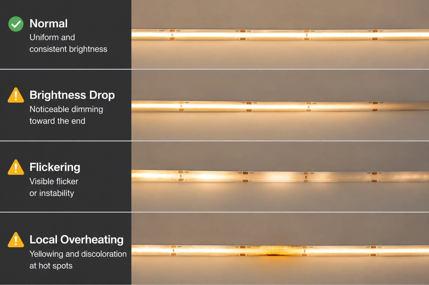
| başarısızlık belirtisi | olası mühendislik nedeni | Önerilen çözüm |
| Şerit boyunca parlaklık azalır | Uzun çalışmalardan veya yetersiz güç dağılımından kaynaklanan voltaj düşüşü | Voltaj seçimini optimize edin, sürekli çalışmaları kısaltın ve güç enjeksiyon noktaları ekleyin |
| Çalışma sırasında aşırı ısı | Yetersiz termal yol veya zayıf ısı dağılımı tasarımı | Termal transferi iyileştirmek için uygun bir alüminyum profil kullanın |
| titreyen veya kararsız aydınlatma | Kararsız güç kaynağı, zayıf kablolama veya güvenilmez konektörler | Sürücü kapasitesini, kablolama kalitesini ve bağlantı noktalarını kontrol edin |
| düzensiz aydınlatma | Yanlış difüzör seçimi veya kötü profil eşleşmesi | Optik tasarımı ayarlayın ve uyumlu profilleri seçin |
| mekanik hasar veya ışık kesintisi | Aşırı bükülme, bükülme veya montaj stresi | Belirtilen bükme yarıçapını takip edin ve PCB'yi dikkatlice kullanın |
Çoğu karartma vakası, bir şerit kusuru yerine eksik bir güç enjeksiyon noktasına kadar uzanır; bu kılavuz Uzun LED şerit ışık kurulumlarında voltaj düşüşleri nasıl önlenir Enjeksiyon aralığını daha ayrıntılı olarak kapsar. Aşırı ısınma kasaları genellikle şeridin güç yoğunluğuna göre küçük veya eksik bir alüminyum profile işaret eder.
En iyi yaklaşım, aydınlatma yapısı kurulduktan ve mühürlendikten sonra performans sorunlarını düzeltmek yerine, tasarım aşamasında bu mühendislik sınırlamalarını (PCB genişliği, güç planlaması ve profil seçimi) belirlemektir.
SSS
Çözüm
çok ince COB LED şeritler sadece dar boyutlarıyla tanımlanmaz. Gerçek mühendislik değerleri, kurulum alanı, görsel görünüm ve performans gereksinimlerinin dengelenmesi gereken aydınlatma entegrasyonu zorluklarını çözmekten gelir.
Ultra ince COB tasarımının temel prensibi, PCB genişliğinin azaltılmasının her zaman mühendislik değiş tokuşlarını içermesidir. Daha dar bir şerit, daha iyi gizleme ve daha fazla kurulum esnekliği sağlar, ancak aynı zamanda bakır kapasitesini, termal marjı ve mekanik toleransı da azaltır.
Başarılı ultra ince LED aydınlatma projeleri eksiksiz bir sistem yaklaşımı gerektirir:
- Gerçek kurulum sınırlamalarına göre PCB genişliğini seçin.
- Elektrik tasarımı sırasında voltaj, akım kapasitesi ve çalışma uzunluğunu göz önünde bulundurun.
- Termal yönetim için uygun alüminyum profiller kullanın.
- Kurulum yöntemlerini mekanik ve çevresel koşullarla eşleştirin.
- Tekdüzelik, görüntüleme mesafesi ve parlama kontrolü gibi optik gereksinimleri değerlendirin.
En iyi ultra ince COB LED çözümü, mevcut en küçük tasarım değil, kompakt entegrasyon, güvenilir performans ve uzun vadeli kararlılık arasında doğru dengeyi sağlayandır.
Mühendisler, PCB yapısı, COB teknolojisi, termal davranış ve kurulum gereksinimleri arasındaki ilişkiyi anlayarak, mobilya, perakende, mimari, otomotiv ve hassas aydınlatma uygulamaları için ultra ince LED sistemleri daha etkili bir şekilde seçebilir ve entegre edebilir.
İlgili Yazılar